I had set aside about four weekends to get this project done, knowing I did not have the luxury of having as much free time behind me, being a busy, new dad and all.

Otherwise, I think one can get this project done in one weekend.
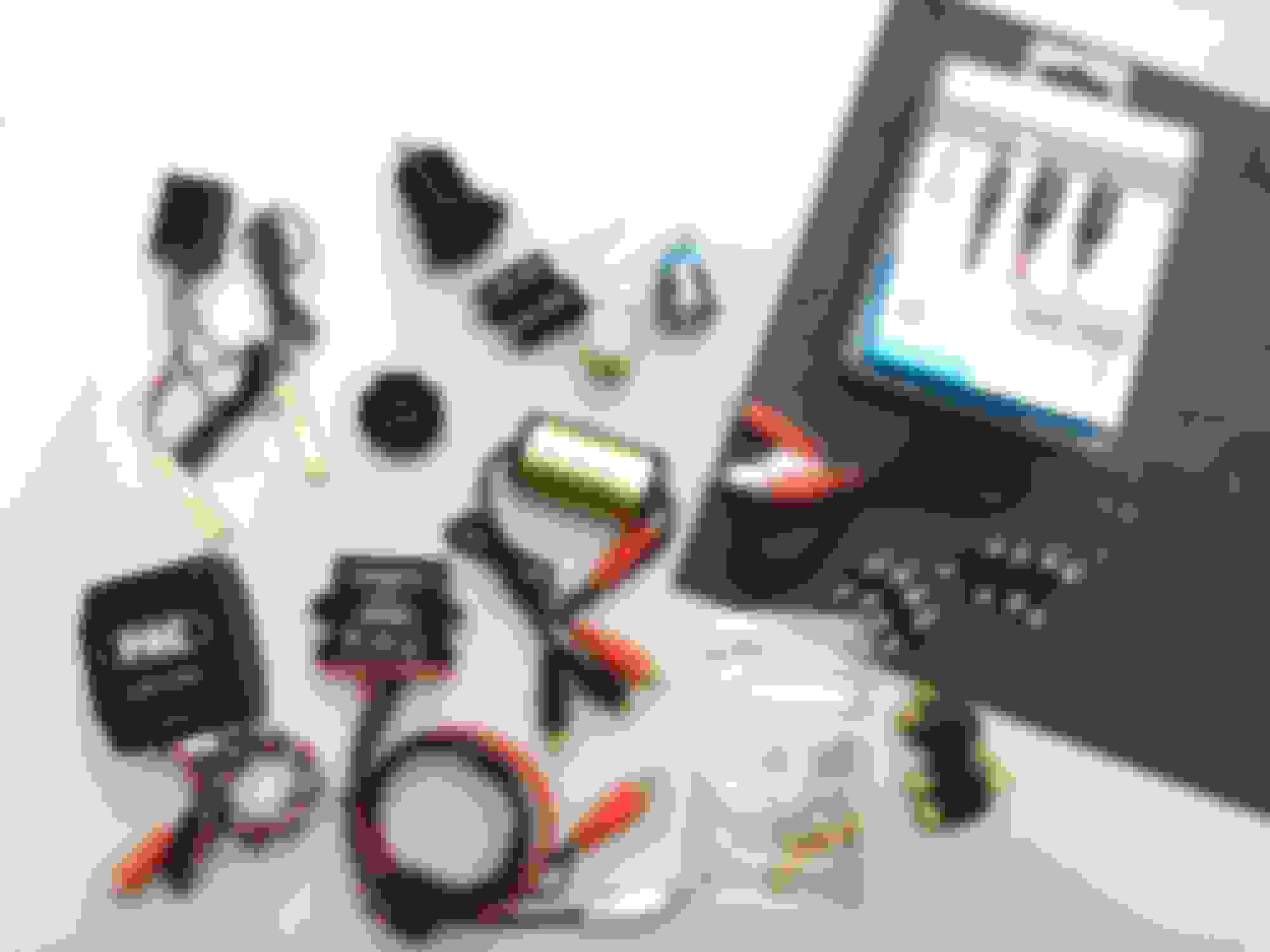
The shopping list:
Pictured below are the major players for my Bluetooth/console mod. Looking at the photo from left to right, top to bottom are the dimmer switch with a few LED strips for console lighting, Auxillary 12volt power connector, a pair of bipolar 100 microfarad DC coupling capacitors, a discontinued 275-218 dual post dual throw 12volt DC relay, a 22mm round stainless steel blue LED lighted latching DPDT switch, a 12"x24"x1/8" ABS sheet, miscellaneous RCA patch cord, 3.5mm stereo split to RCA cable for my iPod and mp3 players, 12v-24v digital voltmeter with red LED display, groundloop isolator aka noise suppressor, male and female RCA barrel connectors, an adjustable 2v-8v signal line driver, the 100ft range Bluetooth version 4.0 module, misc 1/2 watt carbon resistors for the console lighting and the Bluetooth A/B switch LED light and a pair of 2 RCA-F to 1 RCA-M signal combiner.
Not pictured is a small 50-turn, 12-volt potentiometer for brightness adjustment for the console LED lighting, 16" warm white LED strip, a 2 piece normally open magnetic reed switch from Directed Electronics, extra RCA patch cords, color designated male and female bullet connectors, 8th inch and 1/4" spade connectors, 24' various colored 16ga wire, 1' thin floral wire to mount the groundloop isolator, 2-part epoxy glue, nylon wire ties, shrink tubes, 1/2" and 3/4" machine screws, red and black male and female RCA connector ends and Scotch 3M electrical tape.
For the budget-minded Bluetooth mod, you can get away without the LED console lighting, the reed and dimmer switches, the auxillary power connector, voltmeter, the line driver, groundloop isolator, iPod cable, coupling capacitors, RCA combiners, floral wire, epoxy, resistors and the potentiometers.
After gathering all the supplies I needed, I started step-1 by prepping the amp's audio signal for RCA-M output from the factory radio and RCA-F input going into the factory amp.

Audio Signal wires:
The yellow wires are the positive right channel (pins 7 & 10, connector A to the amp).
The yellow wires with violet stripe are the negative right channel(pins 6 & 9, A).
The blue wires are your positive left channel (pins 1 & 8, A).
The blue wires with brown stripes are your negative left channel (pins 2 & 3, connector A on the schematic).
These RCA connectors are where the new Bluetooth and iPod/mp3 signal source will mate to the factory system. With the male and female RCA's connected, as pictured below, system operation can be reversed back to original if I decide to remove the BT system.

Ground, Power and Trigger wires:
Taps to power and ground were made close to the amp to avoid most common noise issues associated with poor ground potential, that may appear in the sound system. The maximum power drain by all the new components is expected to be only 2 amperes or less when in use.
Black 16ga, pigtail leads with color designated, female bullet connectors were soldered to the brown ground wire (pin 4 & 11, connector A on the schematic diagram).
Yellow 16ga, pigtail leads were soldered to the blue with dark green stripe, amp turn on or trigger wire (pin 5, same connector).
And red 16ga, pigtail leads were soldered to the red with yellow stripe +12 volt wire (pin 1 or 9, connector B).
In practice, you should always use female connectors on wires where power source originates from to avoid accidental shorts should it touch exposed bare metal.

All wire splices and connections were soldered for best and reliable performance and all wires were either shrink tubed or wrapped with 3M electrical tape and bullet connectors crimped with proper crimp tools.
Extra precaution was applied to keep + & - inside the RCA connector barrels by placing a separator barrier between both wires.
Once step-1 finished, I was able to listen to the factory system as normal during the next couple of weeks until everything was ready for final hookup. So, if you were wondering, there never was a system down-time during the Bluetooth build process.
.