Step-2
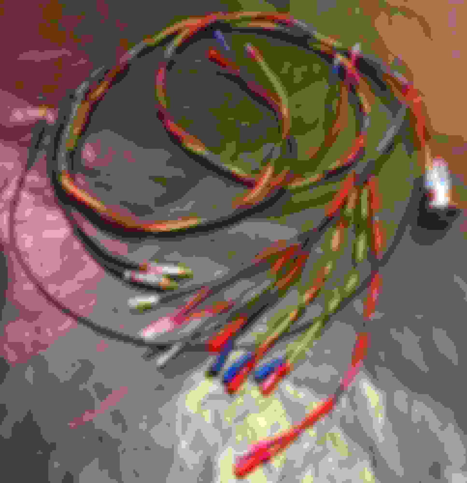
The few available days I have working on this project was spent on building a single-run-wire harness that connects the new console electronics to the power source at the amplifier location. You can tell the directional flow of the electrical power if you notice the type of bullet connector used at the ends of each wire leads.
During the R&D stage, I found the brightness of the switch's built-in LED to be extremely bright and would have lit the entire car's cabin blue while driving at night. I wanted the blue LED ring around the stainless steel Bluetooth switch to match the brightness of the green LED ring around the factory radio volume-****, so one night I brought the Bluetooth switch with me in the CF, along with a few resistors and temporarily connected to battery power. After about 30 minutes, I found the right resistor value that dimmed the blue LED ring to perfectly match that of the radio volume control. You will see what appears to be a black wire attatched to the BT switch. Well, that is actually the correct value, 90K ohm resistor imbedded inside that black shrink tube.
Various shrink tube sizes were used throughout to tie and bundle the wires together. This makes for snaking the harness a lot easier and eliminates jambing under the carpet and other obstacles during installation.
Several measurements were taken between the two points to make sure that none of the harness wire leads where the wires split up near the back of the console to the footwell were neither too long nor too short. And it turned out that I had to make some adjustment to the iPod/mp3 cable. I needed it to be longer so a replacement was in order. The actual length of the wire harness came to 10 feet, end-to-end, from the foot well to the 3.5mm tip of the iPod cable. Power and ground came to only 6 feet. Step-2, Done!
Thanks for looking, everyone!
Next; It will be the cutting and drilling.
.