While the additional features and electronics on the storage console were being worked on during the day, I was able to chip away in completing the component board at night, after putting my son to bed.
Components were all placed on the upper end of the board to avoid creating a large bulge on the footwell carpet once the board is mounted to the cabin side of the factory amp panel. Several trips were made to the Crossfire footwell/amp area to ensure that the board had enough clearance, that it did not interfere with any of the factory wiring or component modules and that it would be stable enough to withstand occasional foot action.
Pictured below (in the foreground) is the input signal switching relay. It is my audio traffic controller that allows me to go from listening to radio, to listening to my smartphone with Bluetooth or to any mp3 device my friends or family decides to bring with them.
Next to the relay are a pair of 100 microfarad, bi-polar, coupling capacitors. They are connected in series with the left and right signal output off the relay. Their main job is to let the AC music signal pass on through to the amplifier and at the same time, block any unwanted DC bias (which could cause popping noise or humm heard though the speakers) between the amp and the relay.
Behind the coupling capacitors is the 4.0 Bluetooth receiver from Exile Audio. The signal received is converted to line level signal and is then sent to the line driver (to boost the signal to 5 volts) located at the very far end of the board.
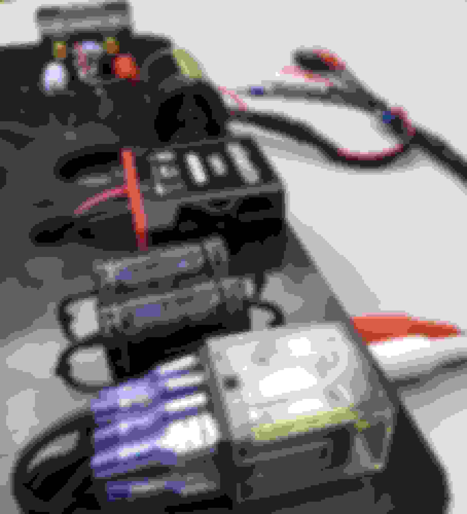
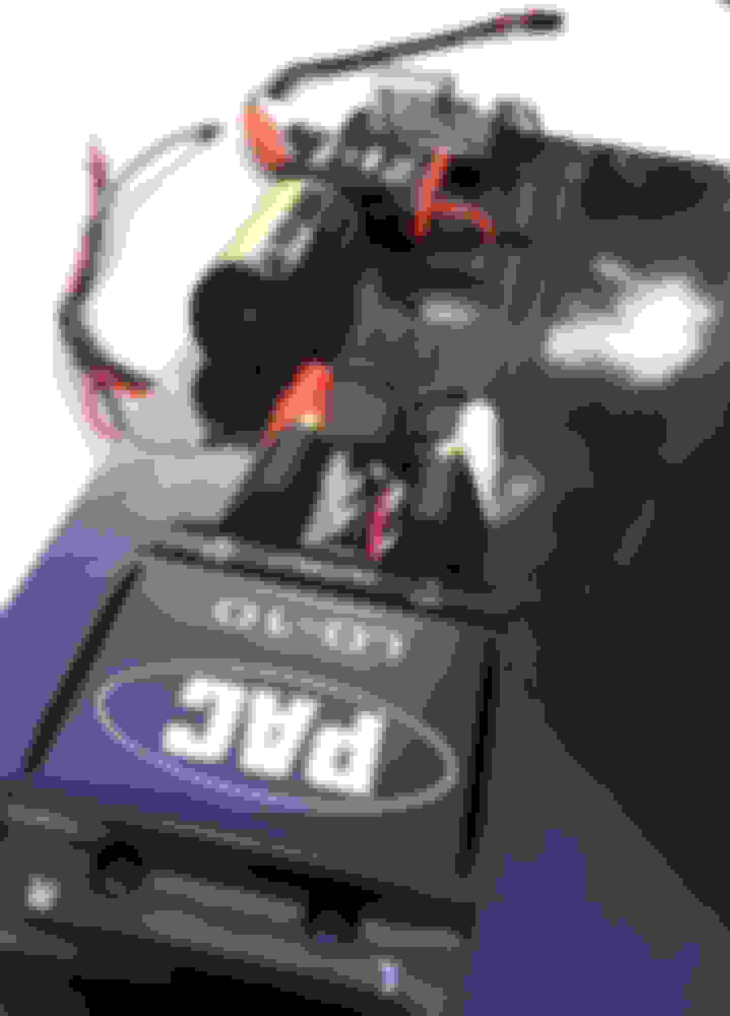
The PAC LD-10 line driver is an essential piece of the puzzle. It's basically there to increase the normally low voltage of any personal/handheld device to the same output level voltage of the factory radio. Mp3 and streaming music would sound anemic when compared to music heard from our OEM headunit because our OEM headunit sends a much higher speaker level signal to the factory amp.
To match the signal level of any Bluetooth/mp3 devices to the OEM headunit, the left and right output voltage level trim **** (shown at the foreground of the picture) can be increased or decreased by turning them up or down.
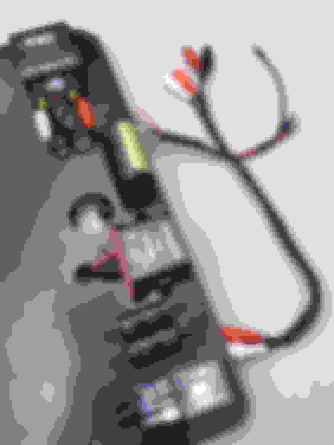
The component board was designed to be removed and installed easily for signal level tuning and for ease of maintenance. There are two stereo RCA cables coming from the board; one is for the signal originating from the factory headunit and it runs to the "A" side of the switching relay. The second RCA cable is from the output end of the switching relay via coupling capacitors and it leads back to the amplifier with either an mp3/iPod/Bluetooth signal or AM/FM/CD signal from the OEM HU. The other set of wires are to connect with the wire harness that leads from the stainless steel A/B source selector switch on the console to switch and power the Bluetooth components.
.