
Under-hood Temperature Profile


Thread Starter
Joined: Aug 2008
Posts: 73
Likes: 0
From: Edwardsville, IL
Decided to instrument under the hood and record temperatures during actual driving conditions. I used a National Instruments DAQ module and my laptop along with (4) thermocouples to read temps. The instrument pack was setup so each thermocouple read and recorded 3 times per second.
https://www.crossfireforum.org/galle...4/ppuser/21897
The "Flight Engineer"!!
https://www.crossfireforum.org/galle...6/ppuser/21897
The thermocouple locations are shown in my gallery and are located in the following:
https://www.crossfireforum.org/galle...5/ppuser/21897
1.) Passenger Side Stock Intake Port Behind the Grill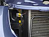
2.) Driver�s Side Stock Intake Tube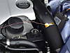
3.) Passenger Side Stock Intake Tube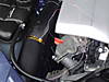
4.) Slightly Above and Behind the Throttle Body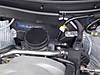
Positions 2 & 3 were chosen to simulate many of the DIY intake systems I have seen on the forum.
I live in St. Louis and today�s test drive ambient temperature ranged from 76 to 81 degrees F. I will try to conduct this same test during colder periods and hotter as environmental conditions allow.
The test drive consisted of a �warmed car� beginning with stop and go city driving, followed by 60 � 70 mph interstate driving, another city driving segment, a second interstate segment and wrapped up with a final city driving segment. These segments are very apparent on the attached graph.
Notables:
1.) Stop and go radiant heat increases all temps dramatically during stops
2.) The Driver�s side intake tube runs cooler at speed but hotter at stops
a.) At stop the increase in Driver�s side temp is most likely attributed to radiant heat from the radiator hose, oil filter and power steering box
b.) At speed there must be additional air flow on this side of the engine compartment that leads to cooler temperatures
3.) Throttle Body Position maintains elevated temperatures through driving range
4.) At speed, the Passenger and Driver�s Side Intake Tube locations are approximately 40 deg. F hotter than the Stock CAI position
5.) Each of the spikes in CAI readings represents a vehicle stop.
I see the entire air intake discussion as a two pronged one: 1.) How much less restrictive are the DIY intake systems that stop behind the radiator than the stock system; 2.) With actual temperature data in hand, how detrimental is the 40 deg increase in behind the radiator systems versus stock? I think I may have access to some instrumentation that could measure the difference in airflow. If so I will add that to this discussion as time permits. I would certainly be interested in �performance savvy� opinions of this data!
Senior Member
Joined: Sep 2007
Posts: 8,014
Likes: 14
From: MOFN, AL, 70 miles from George

Nice work!
Are the TC's actually attached to the intake tubes and the flange in front of the oval radiator tube using Kaptan tape (surface mount TC's?) If so, I
would think you would be measuring the temp of the plastic and not the air in those locations. If anything, they would read false highs, and tend to flatten out the profiles.
Maybe suspending the TC's on an insulating (wood?) dowel in the airstream would be the way to go.
I saw much the same result in a lillte experiment of my own, however using the NI modules is a better, normalized way to go!
I'm not just blowing wind here, I make and design gas and embedded material thermal measurmentsystems all the time. If you are trying to measure gas, the TC must be supported, by a thermal insulator, in the media to be measured so as not to skew the results.
https://www.crossfireforum.org/forum...ad.php?t=27554
Last edited by maxcichon; Sep 21, 2008 at 03:41 PM.

Forum Regular
Joined: Dec 2007
Posts: 427
Likes: 1
From: San Pedro
you should get a scan tool as it is less effort to get the same data.
my cars' intake temp is about 100 deg. at 75 mph with an ambient temp of 70 deg. after the car is comletly warmed up and on the fwy.
CAi is a must have!!!!
my cars' intake temp is about 100 deg. at 75 mph with an ambient temp of 70 deg. after the car is comletly warmed up and on the fwy.
CAi is a must have!!!!
Thread Starter
Joined: Aug 2008
Posts: 73
Likes: 0
From: Edwardsville, IL
The thermocouples are not attached directly to any plastic surfaces. They are offset from these surfaces by 1/2 to 1 inch in an attempt to more closely monitor actual air temps as opposed to "component" temps. Once again, with a 3Hz sample rate, you can see in the attached graph a great deal of "saw tooth" in the data; if they were directly attached, I agree you would see much more smooth curves.
I'm not just blowing hot air either!....I design and install industrial ovens bigger than most suburban homes!
I'm not just blowing hot air either!....I design and install industrial ovens bigger than most suburban homes!
Originally Posted by maxcichon
Nice work!
Are the TC's actually attached to the intake tubes and the flange in front of the oval radiator tube using Kaptan tape (surface mount TC's?) If so, I
would think you would be measuring the temp of the plastic and not the air in those locations. If anything, they would read false highs, and tend to flatten out the profiles.
Maybe suspending the TC's on an insulating (wood?) dowel in the airstream would be the way to go.
I saw much the same result in a lillte experiment of my own, however using the NI modules is a better, normalized way to go!
I'm not just blowing wind here, I make and design gas and embedded material thermal measurmentsystems all the time. If you are trying to measure gas, the TC must be supported, by a thermal insulator, in the media to be measured so as not to skew the results.
https://www.crossfireforum.org/forum...ad.php?t=27554
Are the TC's actually attached to the intake tubes and the flange in front of the oval radiator tube using Kaptan tape (surface mount TC's?) If so, I
would think you would be measuring the temp of the plastic and not the air in those locations. If anything, they would read false highs, and tend to flatten out the profiles.
Maybe suspending the TC's on an insulating (wood?) dowel in the airstream would be the way to go.
I saw much the same result in a lillte experiment of my own, however using the NI modules is a better, normalized way to go!
I'm not just blowing wind here, I make and design gas and embedded material thermal measurmentsystems all the time. If you are trying to measure gas, the TC must be supported, by a thermal insulator, in the media to be measured so as not to skew the results.
https://www.crossfireforum.org/forum...ad.php?t=27554
Senior Member
Joined: Sep 2007
Posts: 8,014
Likes: 14
From: MOFN, AL, 70 miles from George
Originally Posted by jbomar
The thermocouples are not attached directly to any plastic surfaces. They are offset from these surfaces by 1/2 to 1 inch in an attempt to more closely monitor actual air temps as opposed to "component" temps. Once again, with a 3Hz sample rate, you can see in the attached graph a great deal of "saw tooth" in the data; if they were directly attached, I agree you would see much more smooth curves.
I'm not just blowing hot air either!....I design and install industrial ovens bigger than most suburban homes!
I'm not just blowing hot air either!....I design and install industrial ovens bigger than most suburban homes!
On the 2 TC's on the intake tubes, how did you get the tips of the TC's inside the tubes and into the airflow? It almost looks on the passenger side as if the tip of the TC is sticking OUT/AWAY from the plastic tube.
Thread Starter
Joined: Aug 2008
Posts: 73
Likes: 0
From: Edwardsville, IL
The 2 TC's are located on the outside of the stock intake tubes. Once again these positions were chosen to simulate the air temp DIY behind the radiator systems would see. I am now thinking about running at least one TC into the intake system to more accurately measure actual intake temps in the vicinity of the stock air filters.
Originally Posted by maxcichon
Ok, one last question:
On the 2 TC's on the intake tubes, how did you get the tips of the TC's inside the tubes and into the airflow? It almost looks on the passenger side as if the tip of the TC is sticking OUT/AWAY from the plastic tube.
On the 2 TC's on the intake tubes, how did you get the tips of the TC's inside the tubes and into the airflow? It almost looks on the passenger side as if the tip of the TC is sticking OUT/AWAY from the plastic tube.
Senior Member
Joined: Sep 2007
Posts: 8,014
Likes: 14
From: MOFN, AL, 70 miles from George
Originally Posted by jbomar
The 2 TC's are located on the outside of the stock intake tubes. Once again these positions were chosen to simulate the air temp DIY behind the radiator systems would see. I am now thinking about running at least one TC into the intake system to more accurately measure actual intake temps in the vicinity of the stock air filters.
Do you have a way to measure the temps in the throttle body (IAT) to compare them with (all internal/airflow, of course). I would be most interested in finding out the temp RISE from the front to the back!
Thanks again, and keep it comin'!
Thread Starter
Joined: Aug 2008
Posts: 73
Likes: 0
From: Edwardsville, IL
Not dense at all....just a ton of words! I do the same thing all the time!
I agree with you. Now that I have some externals, I want to monitor the heat rise through the intake system. I'll think about this over an Imbevweiser later today and get to it!
I agree with you. Now that I have some externals, I want to monitor the heat rise through the intake system. I'll think about this over an Imbevweiser later today and get to it!
Originally Posted by maxcichon
I guess I'm just a bit dense! After re-reading the 1st post, it clearly says that.
Do you have a way to measure the temps in the throttle body (IAT) to compare them with (all internal/airflow, of course). I would be most interested in finding out the temp RISE from the front to the back!
Thanks again, and keep it comin'!
Do you have a way to measure the temps in the throttle body (IAT) to compare them with (all internal/airflow, of course). I would be most interested in finding out the temp RISE from the front to the back!
Thanks again, and keep it comin'!
Joined: Jul 2008
Posts: 91
Likes: 0
From: New York
A+ for effort and A- for technique. When we measure Forced Draft air temp on a boiler we never mount the thermocouplings on the out side of the air ductwork. You will have to drill two holes, one in the tubing coming from the grill and another, unnoticeable under the engine cover close to the throttle body and insert the thermos there, in the air path to measure temp variation across the two points. Just because the outside of the duct is hot it doesnt necessarily mean the air flow is the same temp. On a stock setup the outside air racing toward the throttle body will pick up temp through conduction, put how much? Next, how do you lower the temp of the engine compartment? One could remove the shroud under the engine or but louvers in the hood . Why go there, just pick up a Needswing or TVT CAI. I think that the shroud prevents air ventilation from occurring properly. I would be equally concerned about the temp of the fuel rail, Pinned between the manifold and the engine cover. Anyhow, what do I know. Iam just a goofy old fart that should be spending my time playing bingo instead of the crossfire.
Last edited by copycat; Sep 22, 2008 at 01:50 PM.

Thread
Thread Starter
Forum
Replies
Last Post
Currently Active Users Viewing This Thread: 1 (0 members and 1 guests)