Waldig tearing apart his throttle body AGAIN>>>>


OK the time is now for the throttle body (TB). Iam installing the modded intake manifolds to test the concept that I have come up with. With the motor torn apart I am going to get the TB checked out to see it there is anything that can be improved on � EASILY����read on.
I took the photos to show what I found and to share it with you all. This will be so that you can see what�s up and not to have to do it, for the first time. Please look at the photos, I have tried to add some comments on the photos to explain what each is showing.
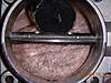
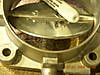
When I took a look at the throttle body I found three areas that needed to be worked on, per my level of interest and intensity. First the inlet has a lip that is about 1/8� thick, which is a big bump. The TB inside diameter is about 3� and that is about 9� around the lip x 1/8� thick which is over 1� square of lip!!!!!!!!!! I took a carbide cutter and air tool to radius the inlet lip to have a smooth taper. I then took 60 grit paper to hand sand the lip till it got the right look / feel. This came out really easy and looks good to my eye, you could use a hand file or hand drill with a cutter. Its aluminum and easy to work.
I ended up getting a smooth edge that reduced the turbulence of the inlet air to the TB. I gained 35 H/P BELOW 2500 RPM with the design of the dual cai for Needswings. It�s the little things that make all the difference, and when you clear away several little things you start making significant gains. Gains without new parts are the best as they are free power literally.
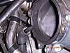
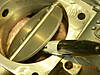
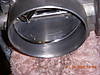
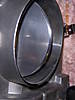
Secondly I looked at the TB butterfly plate. It is a thick round plate that is way thick and has a square profile = turbulence turbulence��.. I took a simple file and slowly hand filed the leading edge to have a taper. I DID NOT USE A DREMEL TOOL TO PREVENT DAMAGE TO THE DIAMETER OF THE PLATE.
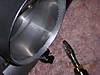
Just cut a 1/8� wide taper on both sides �top and bottom � of the front edge of the butterfly. Do not change the plate diameter, the thickness of the plate is left about 1/3 of its original thickness and is rounded, see the close-up photos. That edge is the one that faces the inlet wye or elbow. I used sandpaper to smooth the front edge and then played with mother�s aluminum � mag polish to shine it up for the squirrel factor in me��. You do not need to touch the rear edge of the plate, its down wind. I also dressed up the long threads of the two anchor screws to smooth them up a bit.
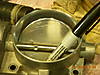
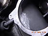
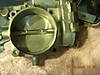
Thirdly I checked the supercharger inlet to see how it looked, its next in line after the TB. The photo shows a large step that was on the lower 1/3 of the s/c inlet, you can feel it big time with your finger, like a curb�.bump. I took several towels to plug up the s/c inlet before attacking this. I removed the inlet gasket, bracket to protect it while I used a small ball / round cutter bit to knock down the lip and clear the lump behind it. This took 2-3 minutes and was easy, a good artist knows when to quit so don�t overdo it. Photo shows all the goodies. Clean the surface and then pull out one towel, clean again, pull out the second towel and clean again. Like easy.
Now check again to see that both towels are out � check again����..
Ill get the inlet back together and then finish the manifolds so that I can test them so that, that can be reported. I must get real results before publishing any data, don�t want to do the �UTAH research� thing to ya..
Please review the photos and Id love to hear your thoughts on this���..WOODY
I took the photos to show what I found and to share it with you all. This will be so that you can see what�s up and not to have to do it, for the first time. Please look at the photos, I have tried to add some comments on the photos to explain what each is showing.
When I took a look at the throttle body I found three areas that needed to be worked on, per my level of interest and intensity. First the inlet has a lip that is about 1/8� thick, which is a big bump. The TB inside diameter is about 3� and that is about 9� around the lip x 1/8� thick which is over 1� square of lip!!!!!!!!!! I took a carbide cutter and air tool to radius the inlet lip to have a smooth taper. I then took 60 grit paper to hand sand the lip till it got the right look / feel. This came out really easy and looks good to my eye, you could use a hand file or hand drill with a cutter. Its aluminum and easy to work.
I ended up getting a smooth edge that reduced the turbulence of the inlet air to the TB. I gained 35 H/P BELOW 2500 RPM with the design of the dual cai for Needswings. It�s the little things that make all the difference, and when you clear away several little things you start making significant gains. Gains without new parts are the best as they are free power literally.
Secondly I looked at the TB butterfly plate. It is a thick round plate that is way thick and has a square profile = turbulence turbulence��.. I took a simple file and slowly hand filed the leading edge to have a taper. I DID NOT USE A DREMEL TOOL TO PREVENT DAMAGE TO THE DIAMETER OF THE PLATE.
Just cut a 1/8� wide taper on both sides �top and bottom � of the front edge of the butterfly. Do not change the plate diameter, the thickness of the plate is left about 1/3 of its original thickness and is rounded, see the close-up photos. That edge is the one that faces the inlet wye or elbow. I used sandpaper to smooth the front edge and then played with mother�s aluminum � mag polish to shine it up for the squirrel factor in me��. You do not need to touch the rear edge of the plate, its down wind. I also dressed up the long threads of the two anchor screws to smooth them up a bit.
Thirdly I checked the supercharger inlet to see how it looked, its next in line after the TB. The photo shows a large step that was on the lower 1/3 of the s/c inlet, you can feel it big time with your finger, like a curb�.bump. I took several towels to plug up the s/c inlet before attacking this. I removed the inlet gasket, bracket to protect it while I used a small ball / round cutter bit to knock down the lip and clear the lump behind it. This took 2-3 minutes and was easy, a good artist knows when to quit so don�t overdo it. Photo shows all the goodies. Clean the surface and then pull out one towel, clean again, pull out the second towel and clean again. Like easy.
Now check again to see that both towels are out � check again����..
Ill get the inlet back together and then finish the manifolds so that I can test them so that, that can be reported. I must get real results before publishing any data, don�t want to do the �UTAH research� thing to ya..
Please review the photos and Id love to hear your thoughts on this���..WOODY

I bored mine out to 76.5mm which is the largest you can really go and still port match the back of the supercharger housing with out having to reweld the mounting points. Opening up the TB is a waste if you don't modify the back of the supercharger housing which is the TB mounting point. Been there done that.
Forum Regular
Join Date: Apr 2008
Location: St. Louis, MO
Age: 41
Posts: 888
Likes: 0
Received 0 Likes
on
0 Posts
I used a ronded edge for strength and stability, knife is too far for me. This is to reduce the turbulence and allow free air flow. Remember the air is going at this point about 120 MPH and friction counts bigtime. Cat is prime assistant, especially the newest rescue RATT Bert, AKA RB. Enjoy, Woody Cleaning up the inlet passage is as far as I go till I have to take things apart further.WW
Cleaning up the inlet passage is as far as I go till I have to take things apart further.WW
Here are new photos of the silver dollar thick plate and the s/c inlet clean up FYI.WW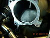
The knife edge would cause separation of the air like the original square cut butterfly plate. this is why I used a smooth rounded edge to smooth the flow a bit.
The floor of the s/c is cut to lower the lip to out of the air path and to blend it into the body better. I did not polish as that was not possible in the car and benefits would be hard to measure, that gain.
Woody
Last edited by waldig; 07-28-2009 at 07:35 AM.
Senior Member

Forum Regular
Join Date: Apr 2008
Location: St. Louis, MO
Age: 41
Posts: 888
Likes: 0
Received 0 Likes
on
0 Posts
fiddle with mine also Waldig. Ported polished the plate and tapered the edge of the throttlebody, also I'm going to try out a posible replacement for the silicone y-pipe.


back side of the throttle plate to give you idea how thick it is.


the y-pipe looks rough i know but i don't have easy access to a band saw and had to use my sawsall . I'm hoping the better angle with allow the air to mix smoother entering the throttle body than the silicone Y, track testing next tuesday to see if it causes any changes in traps on and off.
back side of the throttle plate to give you idea how thick it is.
the y-pipe looks rough i know but i don't have easy access to a band saw and had to use my sawsall
Senior Member
Originally Posted by waldig
Here are new photos of the silver dollar thick plate and the s/c inlet clean up FYI.WW
The knife edge would cause separation of the air like the original square cut butterfly plate. this is why I used a smooth rounded edge to smooth the flow a bit.
The floor of the s/c is cut to lower the lip to out of the air path and to blend it into the body better. I did not polish as that was not possible in the car and benefits would be hard to measure, that gain.
Woody
The knife edge would cause separation of the air like the original square cut butterfly plate. this is why I used a smooth rounded edge to smooth the flow a bit.
The floor of the s/c is cut to lower the lip to out of the air path and to blend it into the body better. I did not polish as that was not possible in the car and benefits would be hard to measure, that gain.
Woody
The square trailing edge has a vacuum and turbulence behind it, a knife edge minimizes this.
I suspect the difference between both designs would be negligible but knife edges are better.
warning. Warning will Robinson. Danger ahead.
The silicone wye was designed by me for a reason.
You NEED flex there. I could use smoother pipes too but you
Can conduct too much stress to the TB support causing it
To shear the coupler gasket. Ask me why I think this is true.
There needs to be little distress on the TB.
Some of the polishers have also posted photos of nice clean
Up of the FAT lip on the TB. That is an inch of edge.
This is significant. Car is crazy strong now between manifold
Design and TB attention. Enjoy. Woody
Last edited by waldig; 08-12-2009 at 10:39 AM.

Join Date: Sep 2007
Location: Saint Charles, Mo.
Posts: 263
Likes: 0
Received 0 Likes
on
0 Posts
Forum Regular
Join Date: Apr 2008
Location: St. Louis, MO
Age: 41
Posts: 888
Likes: 0
Received 0 Likes
on
0 Posts
Woody what did you change on your manifold? also I planned on clamping not not welding the Hard y pipe on with some left over 3inch fuel filer hose that is rather sturdy but allows a little flex. Should keep enough flex at the throttlebody without causing any turbulence. But we shall see!
Last edited by ProjectMayhem; 08-12-2009 at 01:05 PM.
Clean up of the throttle body is more important to lower powered cars as you have less to work with and every bit helps. A 1% gain for me is like a 1.5% gain for you, like that. Restriction is a bad thing for warm air engines, it reduces the efficiency which reduces the horsepower. Woody
If you feel bumps, edges, serious bends, they are impeding the flow of air that you are PAYING to heat up and expand to push your pistons down.
If you feel bumps, edges, serious bends, they are impeding the flow of air that you are PAYING to heat up and expand to push your pistons down.
Originally Posted by Paul Bosslet
Hi all,
Does the cleanup apply to the N/A as well or the SRT only?
Does the cleanup apply to the N/A as well or the SRT only?
Am I implying that Waldig's modded throttlebody sucks more than the stock ones... You can bet your tail I am.
Keep up the great work Woody. You never cease to amaze us.

Thread
Thread Starter
Forum
Replies
Last Post
cjw
Wheels, Brakes, Tires and Suspension
2
10-26-2015 10:26 PM
2005 Ragtop
Wheels, Brakes, Tires and Suspension
7
10-03-2015 03:01 PM
Currently Active Users Viewing This Thread: 1 (0 members and 1 guests)