
Just a thought about how to cool the inlet air

Thread Starter
|
Senior Member
Joined: Feb 2008
Posts: 4,508
Likes: 34
From: VA

I have been thinking that the inlet air to the engine could be cooled, for those that want to get the max power by doing an experiment.
This is an off the wall idea that I have been kicking around and wanted to gather the ideas from the forum to evaluate it. "Splinter" has sent me a great graphic of the heater box air flow path to help evaluate the idea.
The air conditioner has a terrific cooling capacity and I was looking at moving the water lines from the intercooler to include the cars heater core. It goes like this: I believe that the intercooler lines could be connected to the car heater lines so that the water goes from the H/E to the pump to the heater core to the intercooler and back to the H/E. This would be in the summer only. Have I lost ya yet, have faith.
With the A/C turned on; the A/C coil will be cooling the cabin air. By turning on the controls so that the heater is on, this cool air would pass through the heater coil before coming out of the vents and therefore cool the water in it( the water that is going to the intercooler on the supercharger).
Now the heater is rejecting heat into the heater box which is cooled by the air conditioner. If you switch the cooler to cold the air that is cooled will bypass the heater coil and give you normal air conditioning. This seems like a free lunch deal and I dont see the downfall. You will get more power from the cooled inlet air and you will have to give up some power to operate the compressor (A/C).
The airconditioner probably has about one ton in cooling capacity. American cars are more so I believe that Iam conservative here, you all will be the judge of that. A ton of cooling is 2000 pounds of ice melting in one day or 24 hours. That is 288,000 BTU's in 24 hours or 12,000 BTUS per hour. A BTU is the amount of heat needed to raise one pound of water one degree F. Thats a lot, in another way to look at this that the A/C system can provide the cooling of about 80 pounds of ice per hour or about 1.3 per minute.
Its a silly idea possibly, but could be tested by swapping around the heater core hoses to test the thought and a minimum of expense. The proposed cooling method is after the H/E so the A/C should have a significant effect, and it is available anytime without having to carry Ice around.
Ok I said it, what are your thoughts?????? Iam thinking that Brian would be the first to think this through and possibly try it on his baked potato.
By the way you would not have to have the heater settings set to 100% cool or heat as a blend might be enough to cool the S/C before a drag race or so.
Laugh and Enjoy, Woody
Senior Member
Joined: Sep 2007
Posts: 8,014
Likes: 14
From: MOFN, AL, 70 miles from George

I'm not sure, but an automobile A/C compressor is more on the order of .5 ton. And it takes I think 6-10 HP to run it.
TVT can probably shed some light on this:
Dyno run A/C ON vs. Dyno run A/C OFF.
The laws of thermogodammits are harsh.
BUT, I don't know...
TVT can probably shed some light on this:
Dyno run A/C ON vs. Dyno run A/C OFF.
The laws of thermogodammits are harsh.
BUT, I don't know...

Joined: Mar 2008
Posts: 121
Likes: 0
Turning on the heater is an old-school trick that will cool your water temp down on the dyno or the staging lanes. You are correct that it will act as an additional radiator of sorts.
WRT to the A/C, that's another can of worms. IMO, the best application I've seen for A/C utilization is this one:
http://www.killerchiller.com/
I'm looking into it for my E55 AMG, but it would work on any FI car with an air-to-water intercooler setup.
WRT to the A/C, that's another can of worms. IMO, the best application I've seen for A/C utilization is this one:
http://www.killerchiller.com/
I'm looking into it for my E55 AMG, but it would work on any FI car with an air-to-water intercooler setup.
I've been investigating and working this issue for sometime.
All you can do with the current system - IMO and testing - is separate the IC coolant from the engine coolant to stop engine heat transfer thru the liquid - you gain about a 50 deg drop in IC coolant temp and a 15-20 deg drop in IAT.
Other then that - the system is just not efficient enough to reduce IAT's to get even close to OAT - boosting or not boosting - no matter how cold you can get the IC coolant.
Not to Hijack Waldig's tread - but I spent this morning testing dry and wet ice in my IC tank - the best I could do was come up with a recipe for the serious drag racer - and only "IF" they could get staged in hurry from engine start up.
Thread Starter
|
Senior Member
Joined: Feb 2008
Posts: 4,508
Likes: 34
From: VA
After reading the notes above it seems that there are many others plowing this field.
For Brian if he had a 1 gallon of water at 32 degrees and it adsorbed enough heat to get up to 212 degrees it only gained 1520 BTU. If you started with 8 # of Ice you get an additional 144 btu per pound of a total of 1152 btu or an overall heat gain of 2672 btu's. To go from Ice( 8# of the melted equivalent of about 1 gallon) to 80 degree water would be only 1536 btu.
In the same time your a/c generates about 12,000 per hour or 200 btu per minute. This is beginning to look tougher. Lets see if the a/c cools 200 btu per minute and the water flow is 5 gallons per minute ( my wag but youll correct my numbers ) that is 40 # of water per minute or a total of 5 degrees drop.
QED: I have shot my own idea down, Tadaa
Ok but on the other hand I really do not see that the intercooler flows thru the water tank, there are common inlet and outlet connections; however the pumps circulate in their own circuits and I wonder how much actual fluid is intermingled, swap spit as it were.
I do come back on to my original plan to get a cooler engine via a better tstat. I have most of that and need to adjust the computer so that the fan will run and drop the block temp. Typically I get the temp needle to the second mark or a full mark below the middle.
As spock's computer used to say: Working!
Happy fathers day, enjoy Woody
PS Brian what was your delta on the tank design versis the stock set-up?
Joined: Mar 2008
Posts: 121
Likes: 0
Originally Posted by waldig
... Ok but on the other hand I really do not see that the intercooler flows thru the water tank, there are common inlet and outlet connections; however the pumps circulate in their own circuits and I wonder how much actual fluid is intermingled, swap spit as it were...
Originally Posted by waldig
I do come back on to my original plan to get a cooler engine via a better tstat. I have most of that and need to adjust the computer so that the fan will run and drop the block temp. Typically I get the temp needle to the second mark or a full mark below the middle....
Originally Posted by waldig
As spock's computer used to say: Working!
Kudos to you AND BrianBrave for the initiative and creativity.
Senior Member
Joined: Sep 2007
Posts: 961
Likes: 0
From: Shreveport Louisiana/BAFB
I too experimented with dry ice and found out what Brian has in his other post. I didn't have any datalogging software or a thermometer and I had 3x the volume of liquid. The water was cool to the touch, but once the car was running it warmed up fast. Here's the video of the old setup, it was ghetto, but it was cheap and allowed me to experiment. http://www.youtube.com/watch?v=lefNz407oeg
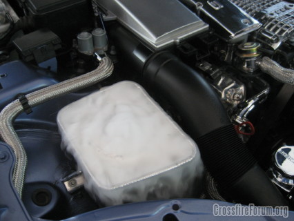
And as Brian stated the dry ice makes some serious smoke, which makes people wonder WTF? I started working on a new/cleaner setup this weekend. Looks like this so far.
And as Brian stated the dry ice makes some serious smoke, which makes people wonder WTF?
Forum Regular
Joined: Jun 2007
Posts: 394
Likes: 2
From: Central CT
You want a bigger heat sink?
How about an Igloo cooler in the passenger seat, feeding the intercooler using a bilge pump!
Check out this guys set up:
http://www.key-ideas.com/AirWaterIC.htm
How about an Igloo cooler in the passenger seat, feeding the intercooler using a bilge pump!
Check out this guys set up:
http://www.key-ideas.com/AirWaterIC.htm

Forum Regular
Joined: Dec 2007
Posts: 312
Likes: 0
I feel that the best bang for your buck would be to seperate the IC circuit, include a decent HE & Pump, as well as upgraded laminova cores in the IC.

Senior Member
Joined: May 2012
Posts: 1,166
Likes: 6
Noob here...I've only owned the car for 3 weeks so still learning....
Also forgive my use of SI units - I'll try imperial and SI where I can....
My previous SLK230 had a different system.
With the new SLK32 - I was looking into a similar (but different) AC Killer chiller option myself - by actually piping the LP side gas directly into the Charge air cooler (pending pressure design and many others of course).
In relation to Waldigs original post - I think it has merit, but I would go that step further and include BB's (and others) idea of a seperate reservior as well. More on that....
In relation to the Killer chiller - it in its current form circa 2012 (given this thread is now getting "old") I have a few comments.....
Design and performance - as waldig seems to be an AC tech - I think you'll understand the idea of COP or coefficent of performance. With AC at the very least you will get 3x the energy consumed, modern inverter designs are now around the 4+ mark. That's because its actually pumping heat in the refridgerant ...not because it's breaking the laws of physics.
A note on the quoted figures below - 200Btu/min is very low. Given the AC uses around 7-8hp (4-5kW)
with a COP it should be "chilling" in the order of 3-4 times that = 15-20kW (850-1150 BTU/min)
.....okay - but I'm not an AC tech.
Air intake.....
I've done some calcs and at 750cfm and post supercharger pressure and temp of 180F (82C) and 14.5 psi boost, you've added 30kW of energy (enthalpy) via the charger. To lower this back to 122F (50C), you need to extract 15kW, but because the SC is still pumping aginst this cooler cavity - your boost is retained at 14.5psi.....fantastic - this is double gain...colder and more dense. In the cooler - the corresponding density has gone from 2.44 to 2.68kg/m3 - or in "atmospheric terms" - the equivalent of 16.8lbs of boost even though the upstream charger is oly pumping out 14.5.
Killer chiller design......
I reckon you will see these become standard on high performance cars. The use of reverse cycle AC in homes (warmer climates) etc and the improvements in design is leading to an appreciation of the benefits of the COP and increases to 5 or more maybe possible (I tink 6 something is the theoretical limit). That is - if you stick an AC pump on your crank - you can utilise the waste heat in the air to your advantage - by a factor of 4 or 5! (or3-4 when you take out the original energy consumed in this closed circuit)
It does add complexity - but as mentioned above - this will/is becoming rudimentary.
However I see some improvements - or given my Noob status - some :suggestions:.
I would put the KC after the normal IC, let the IC do 15kW of work at high dT's (using Waldigs figures below) and then clean up the tail with the KC. Set up the way they have it - once you cool the air - you run it through the IC and it could possibly even warm up again (we dream).
As stated in one of their docs the path of the coolant is
".....Reservoir – pump – heat exchanger – KC unit – intercooler – reservoir......"
(X) Waldig your idea of the Cabin air is worth merit, assuming the heater coil is downstream of the AC evaporator, otherwise it's just a simple cooler.
Now to one pentultimate design for SRT6/SLK32
But, after considering the above - and the (still outstanding) associated design/pressure risks with the direct cool option - maybe utilising the seperate circuit and retaining the IC cooling effect (by utilising the flowing air past the car)....would still have its merits
Also forgive my use of SI units - I'll try imperial and SI where I can....
My previous SLK230 had a different system.
With the new SLK32 - I was looking into a similar (but different) AC Killer chiller option myself - by actually piping the LP side gas directly into the Charge air cooler (pending pressure design and many others of course).
In relation to Waldigs original post - I think it has merit, but I would go that step further and include BB's (and others) idea of a seperate reservior as well. More on that....
In relation to the Killer chiller - it in its current form circa 2012 (given this thread is now getting "old") I have a few comments.....
Design and performance - as waldig seems to be an AC tech - I think you'll understand the idea of COP or coefficent of performance. With AC at the very least you will get 3x the energy consumed, modern inverter designs are now around the 4+ mark. That's because its actually pumping heat in the refridgerant ...not because it's breaking the laws of physics.
A note on the quoted figures below - 200Btu/min is very low. Given the AC uses around 7-8hp (4-5kW)
with a COP it should be "chilling" in the order of 3-4 times that = 15-20kW (850-1150 BTU/min)
.....okay - but I'm not an AC tech.
Air intake.....
I've done some calcs and at 750cfm and post supercharger pressure and temp of 180F (82C) and 14.5 psi boost, you've added 30kW of energy (enthalpy) via the charger. To lower this back to 122F (50C), you need to extract 15kW, but because the SC is still pumping aginst this cooler cavity - your boost is retained at 14.5psi.....fantastic - this is double gain...colder and more dense. In the cooler - the corresponding density has gone from 2.44 to 2.68kg/m3 - or in "atmospheric terms" - the equivalent of 16.8lbs of boost even though the upstream charger is oly pumping out 14.5.
Killer chiller design......
I reckon you will see these become standard on high performance cars. The use of reverse cycle AC in homes (warmer climates) etc and the improvements in design is leading to an appreciation of the benefits of the COP and increases to 5 or more maybe possible (I tink 6 something is the theoretical limit). That is - if you stick an AC pump on your crank - you can utilise the waste heat in the air to your advantage - by a factor of 4 or 5! (or3-4 when you take out the original energy consumed in this closed circuit)
It does add complexity - but as mentioned above - this will/is becoming rudimentary.
However I see some improvements - or given my Noob status - some :suggestions:.
I would put the KC after the normal IC, let the IC do 15kW of work at high dT's (using Waldigs figures below) and then clean up the tail with the KC. Set up the way they have it - once you cool the air - you run it through the IC and it could possibly even warm up again (we dream).
As stated in one of their docs the path of the coolant is
".....Reservoir – pump – heat exchanger – KC unit – intercooler – reservoir......"
(X) Waldig your idea of the Cabin air is worth merit, assuming the heater coil is downstream of the AC evaporator, otherwise it's just a simple cooler.
Now to one pentultimate design for SRT6/SLK32
- Stage 1 Split the cooling circuits and have seperate reserviors.
- Stage 2 - Pipe the intercooler water into the cabin heating and utilise the initial coooling capacity of the AC (although the cabin would get hot during racing....in my case = put the top down or open the windows) Pending the answer to (X) above.
- Stage 3 Put the KC on but after the IC and before the cabin heater.
- Utilise the Cabin/KC switch so that if the Missus is complaining - bypass the KC.
But, after considering the above - and the (still outstanding) associated design/pressure risks with the direct cool option - maybe utilising the seperate circuit and retaining the IC cooling effect (by utilising the flowing air past the car)....would still have its merits
Last edited by Billy22Bob; Jun 23, 2012 at 05:05 PM.
Senior Member
Joined: May 2012
Posts: 1,166
Likes: 6
done a little schematic.
I guess one obvious downside is that if the Supercharger isnt "warmed up" - your cabin heater might be a little lack lustre.
I've shot off an email to the KC guys.
Aside - cooling the fuel wouldnt b as effective - since due to the AFR mass ratio being 12-14....any cooling you do on fuel will only have an effective reduction of 1/12th that of cooling the air.
Having said that - due to contacting patterns an any Heat Exhanger - it might be possible to chill the fuel to 40F (consistently) than it is the air.
s
Last edited by Billy22Bob; Jun 23, 2012 at 07:23 PM.
Senior Member
Joined: Mar 2008
Posts: 14,606
Likes: 39
From: IN
3 year old thread my friend. A lot has been done since then. I have the seperation kit on both my cars now, and will soon experiment with a meth set up on my coupe. Rob sells a simple seperation kit at Needswings website. I have been to the drag strip with guys who have ran the tanks, put ice on the SC, etc etc. I still matched up very well, with nothing. So, I do like the seperation kit set up, but not wasting my time on any cooling mods. I don't round track, just drag race from time to time...so it works for me...
Senior Member
Joined: May 2012
Posts: 1,166
Likes: 6
If someone can please humour me.
I'm looking for some data to "tune" my model.
part attached - I have an intake model as well.
But still looking for drawings of of the charge air cooler to do theoretical calcs.
I need some stable AIT's v dT's across either the SC or the IC (same thing as far as temperature is concerned) with gpms/lpm.
Some rpms' would be helpfull.
This points to heat rejection from the Charge Air Cooler. Doesnt matter if its a supercooler or a mod'd IC. As long as its stable and representative.
My calcs are saying 15-20kW heat rejection would be a good start.
I know Waldig did some data collection but possibly on the Johnson pump - doesnt matter - I 'm just trying to get a feel for the numbers..
Last edited by Billy22Bob; Jun 24, 2012 at 03:23 PM.
Senior Member
Joined: Dec 2006
Posts: 6,349
Likes: 17
From: Murfreesboro, TN
If someone can please humour me.
I'm looking for some data to "tune" my model.
I need some stable AIT's v dT's across either the SC or the IC with gpms/lpm.
Some rpms' would be helpfull.
My calcs are saying 15-20kW cooling capacity should be a good start.
I know Waldig did some data collection but possibly on the Johnson pump - doesnt matter - I 'm just trying to get a feel for the numbers..
Senior Member
Joined: May 2012
Posts: 1,166
Likes: 6
It might be a silly question - but "off the bat" I cant see an obvious answer...
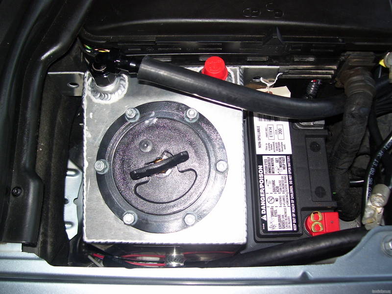
Why is there an expansion line to the top of the SC reservior, when 12 inches previous there is a "suction" from the same reservior.
Couldnt this suction act as a send receive line or is there some sort of check valve in it?
Then you could simply disconnect the small expansion line.
The other thought I had in addition to this is, since the SC water doesnt/shouldnt get to the heady heights of 212F+++ that the Radiator water could....(as noted in BB's posts onthe subject) its requirement for expansion is a lot less (maybe +4% at 211F). 4% in 2L/quarts is 80ml (compared to zero) or just under three ounces. If you were to disconnect the expansion tube (as per above), you could isolate the SC system simply by gluing (you could even do it with a "temporary" glue) a 1 1/2 inch thin walled PVC tube/annulus (whatever largest fits in the cap hole) around the riser from the SC riser pipe. I tried to illustrate.
You'd have to drain and dry around the area to glue of course. This tube would extend to above the high water line in the reservior (as close to the base of the cap as possible), thus effectively segregating the two systems. No need for another tank - the tube is your new tank......
(?)
Last edited by Billy22Bob; Jun 25, 2012 at 08:55 AM.
Ambient is your enemy - the only way to beat it is by sapping hp...
Senior Member
Joined: Apr 2010
Posts: 2,404
Likes: 8
From: Mendocino, CA
It might be a silly question - but "off the bat" I cant see an obvious answer...
Why is there an expansion line to the top of the SC reservior, when 12 inches previous there is a "suction" from the same reservior.
Couldnt this suction act as a send receive line or is there some sort of check valve in it?
Then you could simply disconnect the small expansion line.
The other thought I had in addition to this is, since the SC water doesnt/shouldnt get to the heady heights of 212F+++ that the Radiator water could....(as noted in BB's posts onthe subject) its requirement for expansion is a lot less (maybe +4% at 211F). 4% in 2L/quarts is 80ml (compared to zero) or just under three ounces. If you were to disconnect the expansion tube (as per above), you could isolate the SC system simply by gluing (you could even do it with a "temporary" glue) a 1 1/2 inch thin walled PVC tube/annulus (whatever largest fits in the cap hole) around the riser from the SC riser pipe. I tried to illustrate.
You'd have to drain and dry around the area to glue of course. This tube would extend to above the high water line in the reservior (as close to the base of the cap as possible), thus effectively segregating the two systems. No need for another tank - the tube is your new tank......
(?)
Here's another way to do it.
Senior Member
Joined: May 2012
Posts: 1,166
Likes: 6
interesting picture....not sure if there's an outlet at the bottom to the hoses underneath - I can only guess so - therwise it wouldnt work.
Thanks
But if I can rephrase/refocus....is there a check valve in these lower reservior tubes so that they only draw form the reservior?
If not, what is the thinking between the larger lower and upper (smaller) pipes?
Are the upper ones in case of a "steam/boiling" event - hence they come from the top of the system, but most of the time the lower pipes draw and suck any 4% system expansion.
(PS 4% expansion from 10L = 400mls)
Senior Member
Joined: Apr 2010
Posts: 2,404
Likes: 8
From: Mendocino, CA
interesting picture....not sure if there's an outlet at the bottom to the hoses underneath - I can only guess so - therwise it wouldnt work.
Thanks
But if I can rephrase/refocus....is there a check valve in these lower reservior tubes so that they only draw form the reservior?
If not, what is the thinking between the larger lower and upper (smaller) pipes?
Are the upper ones in case of a "steam/boiling" event - hence they come from the top of the system, but most of the time the lower pipes draw and suck any 4% system expansion.
(PS 4% expansion from 10L = 400mls)
Thanks
But if I can rephrase/refocus....is there a check valve in these lower reservior tubes so that they only draw form the reservior?
If not, what is the thinking between the larger lower and upper (smaller) pipes?
Are the upper ones in case of a "steam/boiling" event - hence they come from the top of the system, but most of the time the lower pipes draw and suck any 4% system expansion.
(PS 4% expansion from 10L = 400mls)