When you click on links to various merchants on this site and make a purchase, this can result in this site earning a commission. Affiliate programs and affiliations include, but are not limited to, the eBay Partner Network.
GeneralThis section is threads for discussion that is not related to the Crossfire or other cars. It can be about sports, movies etc. - But NO POLITICS please
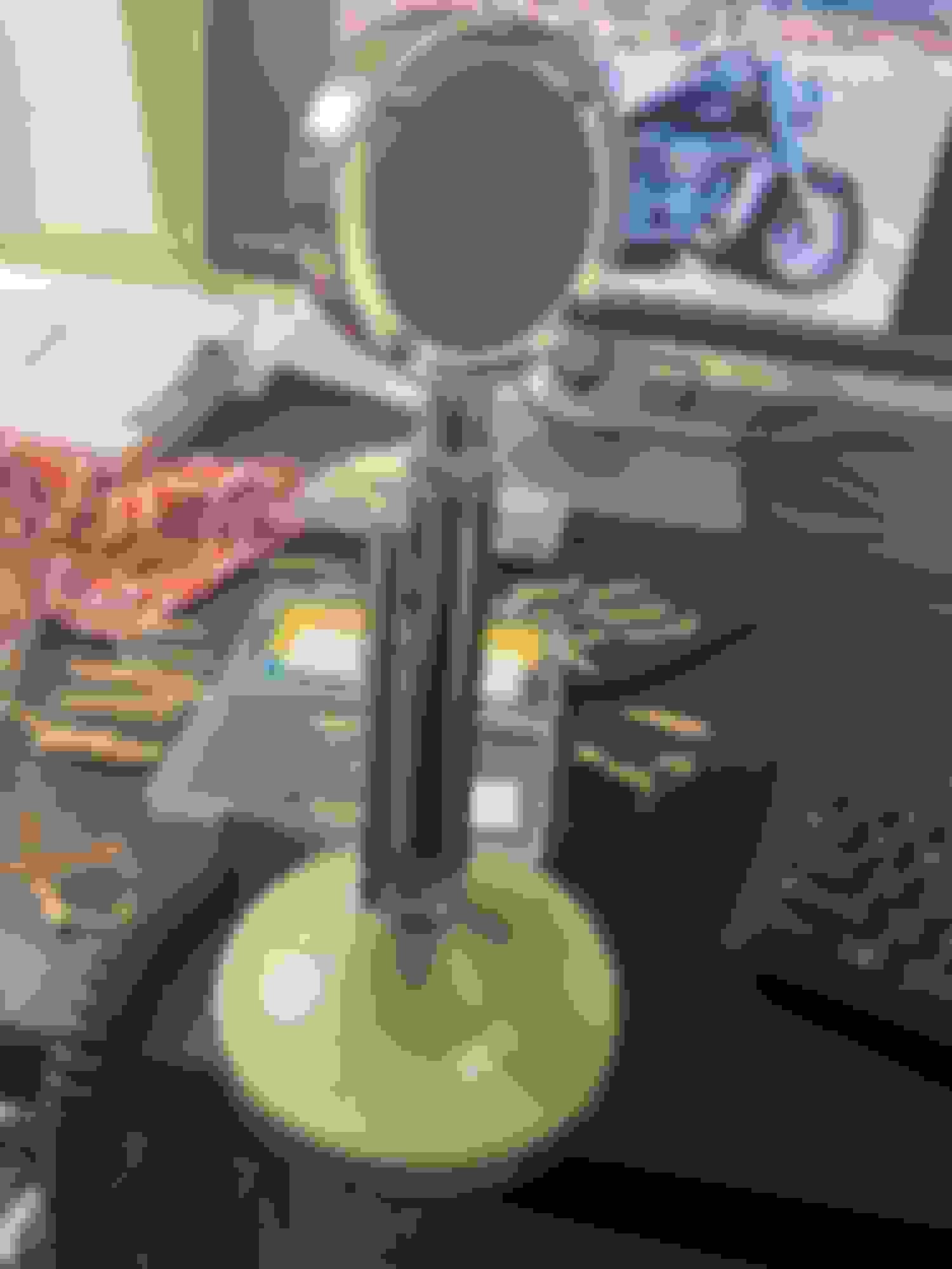
Ok, gotta finish the mic amp and speech amp stages today. My 50 year old D104 mic, that I found on eBay for $35, came today. It is filthy, old, and the cable is crap but it does work if you bypass the cable.
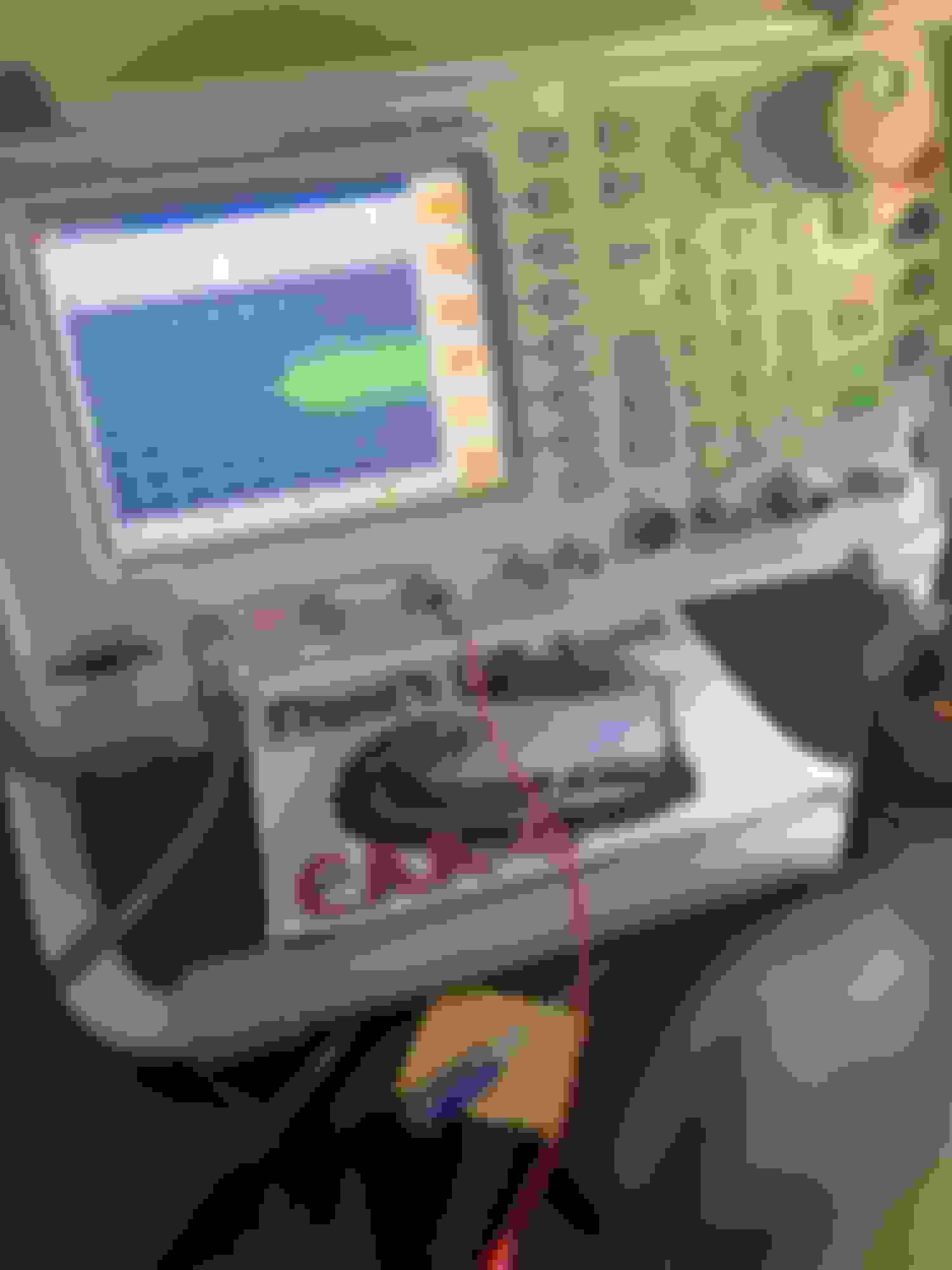
I happened to have the Aeroflex here for the weekend, which is helpful, as it has an OUTSTANDING general purpose scope in it, in addition to the suite of RF test functions. Second photo is the D104 wired temporarily to the CH1 scope input. The mic cartridge is almost unmanageably sensitive on the '3920, it sounds good over the test channel, but it's a bit echo-y even at low setting. I think my transmitter will be way less sensitive so probably not going to be a problem, the 3920 is an outstanding instrument.
So the cathode follower in the audio chain is a bust. I used the wrong tube and the article I took the idea from was theory, I don[t think that project was built.
I need more audio than the 12ax7 can give in cathode follower. So next weekend I will change that stage to a common cathode amp and use a resistor network to match the input to the balanced modulator.
Had I used a 6ea8 I'd be ok. But I don't like the first section of the 6ea8 and that's why I did nto use it. The promise of the famous dual triode audio tube does not pan out in cathode follower. Not for the drive level i need.
Scope shows the output to the level pot from the first stage.Display is of my voice using the D104 mic, which I also spent time on today, rewiring it for "classic tube" transmitter input. The output of the CF was clipping on the negative peaks above about 200mV. The output of the CF was clipping on the negative peaks above about 200mV. But still, had a fun day. It's fun to see how things work, and if it was easy, I'd not feel like I was doing ANYTHING.
Did a little work on the transmitter. Put in the ceramic mounts for the balanced modulator and drilled two boards (so I have a spare).
The balanced modulator will be built "dead bug" style using the copper surface for a ground plane, making it stable. The screws are in ceramic insulators, so the board is not grounded, there will be ONE ground to the board, to prevent ground loops.
So the dead bug version of the balanced modulator is done. The prototype was unstable but gave me almost 40 dB of suppression. THIS version is rock stable, but gives me only 26 dB of suppression. DAMN! I wanted a challenge, I got one.
Based on the fact that the trimmer cap is almost useless, I suspect stray capacitance is the culprit. I won't give up. Some guys in the radio club said "No one can build an SSB transmitter at home" - I took that as a challenge, one I will not walk away from. I'ts going down to 14F tonight here in Texas, what ELSE do I have to do this weekend?
So, the reason the capacitor was ineffective was not because of stray capacitance, but the cap itself is bad out of the box. I changed it and have around 50dB suppression. REwinding the toroid coil got my sidebands stronger - so it's working but the new cap, which came from the same bag of eBay parts, is not really right. I am going to find a new cap and buy it, sometimes, surplus parts just don't perform in critical applications.
As to a receiver build, I bought a nonworking Heath HR1680 and got it working to specs (it is seen in the first three posts in this thread), and I've got to modify it for AM operation. BUT, this transmitter will only do 30-50 watts when I am done, so I was going to build an amp to 200-400 watts after this is done. But I will admit, last week, I was thinking about building a matching receiver. My 1680 is solid state, it would be appropriate to have a tube-type receiver. So maybe................
I did it. 61 dB of carrier suppression. A lot of messing with capacitor values, wound THREE output transformers, struggled for three weeks, but I have my carrier down 61 dB with 32 to 40 dB of sidebands above that. I will now put it in the transmitter and see how it interacts with the other stages. If it acts poorly in the transmitter, well, Im' not giving up.
The big trick was getting the new trimmer capacitor from Mouser Electronics and then playing with the audio input network. Also, I did not realize how fussy the ring is to loading effects from the audio driver , I had to use a smaller input capacitor than expected, once I did that, my sidebands looked better.
I was told, "No one can build an SSB transmitter on their own". I might be about to prove that guy wrong, but can't say for sure, yet.
Things have changed again, but today was a big day, driving the transmitter with the D104 "lollipop" mic is working, finally..
The Cathode follower after the carrier oscillator is gone. I now have double sideband suppressed carrier at my IF frequency, this is a big step. My carrier suppression is over 60 dB and I have 45 dB of sidebands above the suppressed carrier.
The schematic and design have changed a bit.
Last edited by pizzaguy; Jan 21, 2024 at 05:30 PM.
I just made a simple capacitor change and got 52 dB of sidebands above the carrier. (That means the sidebands are 316 times the voltage level of the carrier - amazing.)
Amazing. Seems no one building from scratch anymore. I'm a ham as well. In Houston. Tech only class. Been in radio since ten or so. Did lmr, broadcasting etc... nice project you have going there.
Are you near shady shores air strip? I'll be driving the SRT6 up sometime soon hopefully.
Amazing. Seems no one building from scratch anymore. I'm a ham as well. In Houston. Tech only class. Been in radio since ten or so. Did lmr, broadcasting etc... nice project you have going there.
Are you near shady shores air strip? I'll be driving the SRT6 up sometime soon hopefully.
Thats 30 miles north of me, about 40 minutes drive
Im in Hurst up by Colleyville.
OK, good progress so far. What I learned today: The Balance modulator loss is 14 dB. More than I think is right, but the prefilter amp is giving me 12-14 dB gain so I guess we are good. I know what current I need at 320 volts to operate the oscillator and prefilter amp. ( see schematic diagram below)
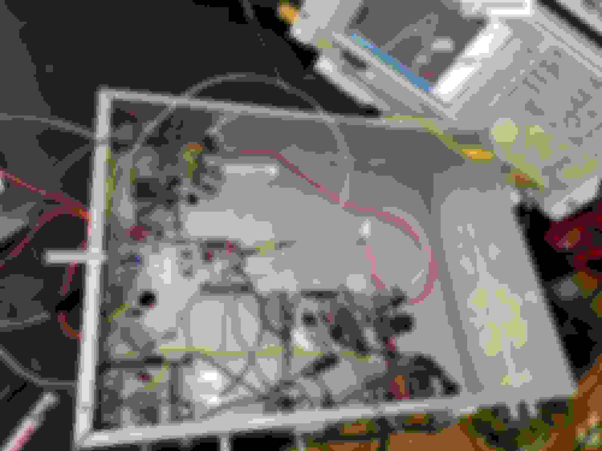
The filter sure works, I am driving the spectrum analyzer with the output of the filter, note how on the right side of the spike, there is no signal, that is the upper sideband, only the lower sideband is present. Mic audio is from my PC speakers playing a Youtube video with my transmitter mic gain wide open. (See picture with underside of transmitter and spectrum display)
I expected a challenge and this has been that. I believe I started construction around December 17 but serious work started on Christmas weekend. Making accurate measurements of gains and losses is a challenge, as my test equipment is 50 ohm input, and these are high Z tube circuits running between 400 and 10,000 or more ohms.
Last edited by pizzaguy; Jan 27, 2024 at 07:46 PM.
So the design has changed again, I need an amplifier to make up for the losses in the filter and balanced modulator (and to compensate for the fact that the carrier oscillator is running kinda "light" - this gives better stability, which is super important in SSB and CW operation). So there will be both a pre and post filter amplifier, I've actually duplicated the same circuit.
I've had issues with my RF level measurements as my home made probe's diode burns up due to how strong the signal is after my pre filter amp! (Im proud of that stage, as I designed it myself). This caused me to think I roasted that tube - I did have it biased wrong and the screen dissipation was very close to exceeding the tube's specs - but its not damaged, and I added two resistors (the 47k and 22K) to stabilize the screen and lower the screen current. It does not appear it cost me any gain, either.
I ALSO found out that my meter might not be reading correctly as it appears it does not understand RF even when rectified (I will talk about that again below). I've been in component level electronics, even worked as a repair tech for 25 years and I've learned SO MUCH these past weeks. This is so much fun.
Again, I thought I burnt up the pre filter amp tube, but here is a copy of a post I made on another forum, I will simply use this text to round out tonight's update:
The Pre-filter amp is FINE. I blew the diode in the probe again. The amp is putting out so much voltage, it nukes the diode but not instantly and it does not always destroy the diode. The diode conducts heavily in an "avalance" or "zener" mode which means it "goes short" at high RF voltages but when those voltages are removed, if done quickly, the diode either is still OK (so it measures the carrier generator level fine, giving me the idea the probe is fine) or it goes 100% short, which it did today which is how I caught what was really going on.
I found that if I go from a 1N34A to a 1N914, it tolerates high levels better and if I go to a 1n4007, it suffers no damage. Either the diodes are avalanching, or the meter I am using does not understand high RF voltages even when rectified. But the 34A is the only one that is accurate. Accurate, but not tolerant of more than about 3 volts of RF. And as I said, my meter may not like RF and I think THAT is also part of my problem.
In any case I am going to borrow a Simpson 260 which I KNOW can take 4mHz RF. Next weekend I willl get to the bottom of it.
In any case, the pre filter tube is not destroyed by overvoltage - I did not see how it could be. IT is fine, but I did change that stage to 250v and added a stabilizing resistor network (the 20k and 47k resistors) to the screen circuit to throttle the tube back within specs, it was at 95% of screen dissipation before.
I built the post filter amp today as well, but was too crimped for time to test it.
I also added the permanent filament transformer and moved all transmitter tubes over to it, reserving the bias/filament transformers' filament winding for the outboard VFO's tubes and pilot lights.
I learned a bit about how small signal diodes can fail - I had no idea they could act is such unpredictable ways, and I did component level repair for 25 years.
Anyway, today was encouraging and next weekend I MIGHT be able to plug in the external VFO and generate an actual 40 meter (7 mhz) signal and hear myself on my receiver! I do not expect good audio or very linear performance, as the ALC is not built yet (gotta wait to get the driver amp and final amp built for that), but it would give me a feeling of accomplishment.
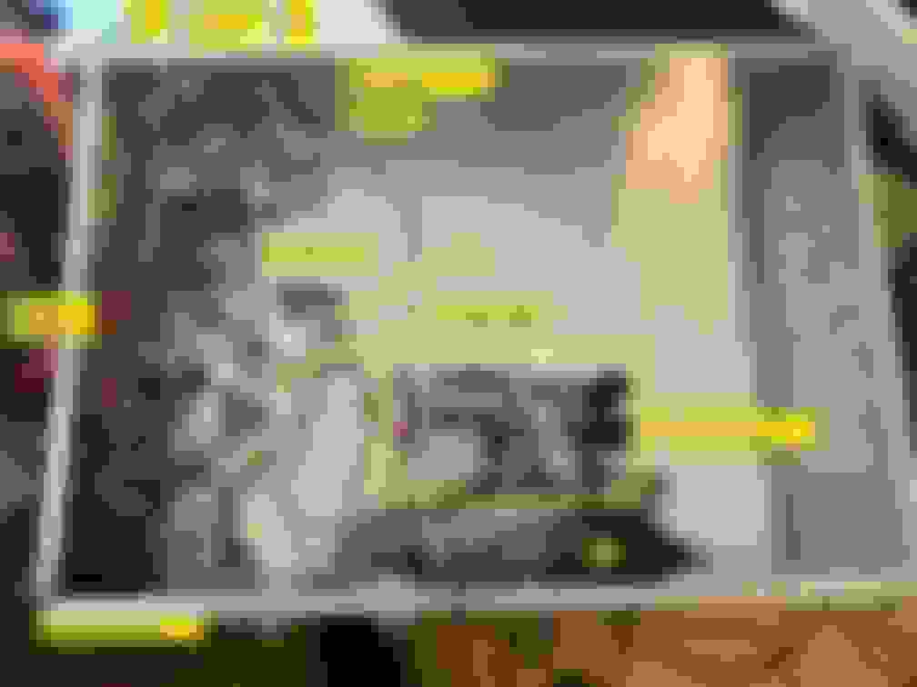
Photos so far, note how (IMO) the post filter amp construction is prettier than the pre filter amp as I knew when I built the stage that it was verified to work as designed (cause it's a copy of the prefilter amp), and I could look at the pre filter amp and plan it better. As I've said before, this is a transmitter NO ONE has built before.
So I built, for larger signals, a new probe and made an analog meter from a 50 microamp movement I found on Amazon.
I modded the new probe to be less sensitive, which means it can measure much larger signals, but it does not read directly in volts and had to be calibrated with an accurate signal generator.
I did this last weekend and tested it yesterday. I can switch the probe over to the digital meter and measure WEAK signals or connect it to this box and measure LARGE signals. But again, even on the digital meter, 1 volt of RF reads on the digital meter as 180mv or .18 volt. This is because, again, I built it to be less sensitive so: A) It can take more voltage and B) It loads (or disrupts) the circuit it is measuring a LOT less than the other one.
GOOD NEWS/BAD NEWS:So the analog meter works wonders. I'v verified my 6au6 amp is KILLING IT. 120mv in, 1.5volts out into a capacitor that was feeding a dead short on the filter. I will get a lot more when feeding a good load.
Unfortunately, the input pin on the crystal filter is grounded/shorted. This is a new development in the last few weeks. I KNOW that filter worked not even three weeks ago. I will not object to the eBay seller, as it was working and this is a 40 year old part (more like 45-50 years, really, as that product was discontinued in 1976 or 77.)
I went on a "Vintage Heathkit Repair" page. Found out a shorted input pin happens a lot and often, disassembly of the filter clears the short but so far, no one has figured out what is going on.
It's a sealed, soldered together unit and not easy to take apart. I found another one on eBay for $23 including shipping. Not sure which way I want to go but at least I can measure RF voltages easier now, I know my amp works, I know why my measurements have not made a lot of sense and the transmitter is working other than the filter has now failed (after 40+ years, we can expect failures with these old parts).
EDIT: I will probably just buy another filter as the seller is now offering the one above for $19 including shipping.
So, a step forward with a step back - still, I am super proud of my 6AU6 tube amp (with a 45 year old NOS tube I paid $9 for) as I designed it myself and it WORKS. I know I have too little signal coming out of the filter (I mean when I get the new filter in) but a second 6AU6 stage will get me up to the 2 volt or 5 volt level the mixer needs (it wants 2 or 5 depending on which grid of the mixer tube I feed it to).
Im learning a lot (and re-learning as I knew tube theory really well as a teen ager). Honestly, this is the most Ham Radio fun I've had since the 1970s.
Last edited by pizzaguy; Feb 11, 2024 at 07:26 PM.
So I ordered another filter - shorted on the input as well. From what I'm told, this is common with these. So I got disgusted and dropped the project and enjoyed the early spring here these past two weeks. I've put about 100 miles on Animal, just running around Fort WOrth.
Today, I went back to it and took the failed filter apart, the one that worked for a while. I used too much heat and may not be able to get it back together properly, but as guys on the Heath pages said, taking it apart removed the short. Now I know how to take the 'new' one apart AND I have two filters of parts now as well. This means that if any crystal has failed, or does fail, I have parts.
Next weekend, I will get back into this and proceed, as the forecast is for a cool down by next weekend.