
TVT300 Installation how-to

Thread Starter
Joined: Mar 2010
Posts: 231
Likes: 0
From: Minnesota
Thanks to Rudy, I managed to score a sweet deal Mr Tazz's old TVT300 kit that he no longer needs since he added another 2 cylinders and a supercharger to his Crossfire.
While the parts I bought from Rudy didn't come with any installation instructions, everything was pretty straight forward using a combination of advice from Rudy and the Crossfire service manual I downloaded from this wonderful site. I figured that since I like taking pics, I might as well document the process for anyone else who might want to install this kit themselves.
I'll try to give the best instructions I can to help anyone else out who might be considering doing this themselves in the future.
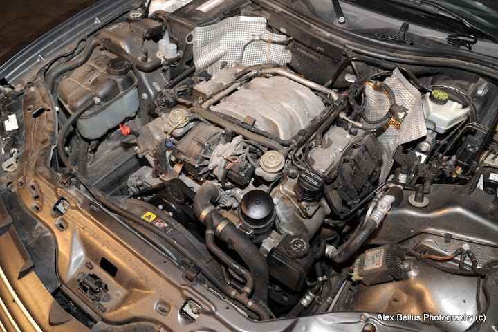
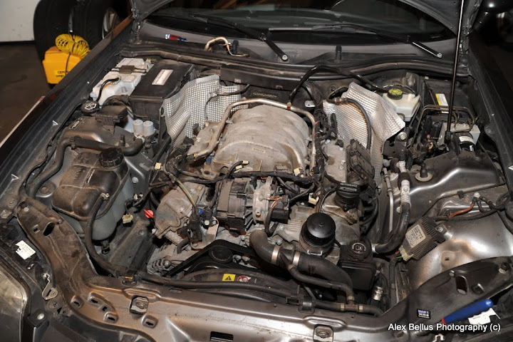
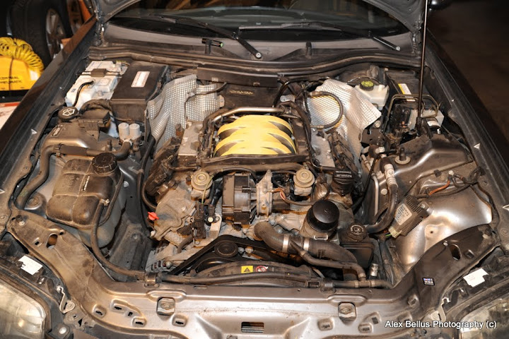
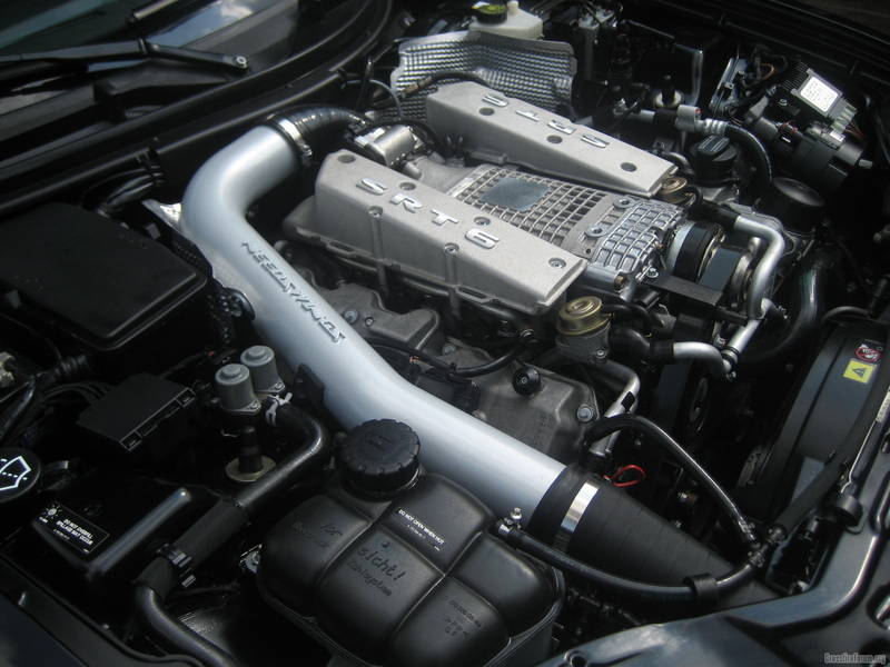
First off, here's a pic of the stock engine:
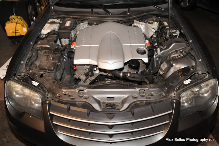
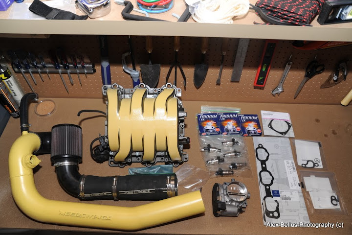
And the parts I bought from Rudy to install (stage 2 ported and polished intake manifold, 74mm throttle body, Needwings Single CAI, 17 lb/ft injectors, and NGK spark plugs, plus new gaskets for everything).
First step was to remove the stock airbox and intake tubes.
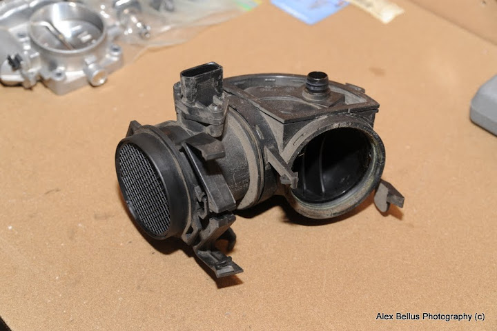
Next, I removed the MAF and intake piece that connects to the throttle body.
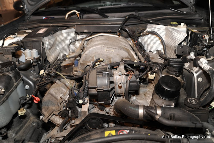
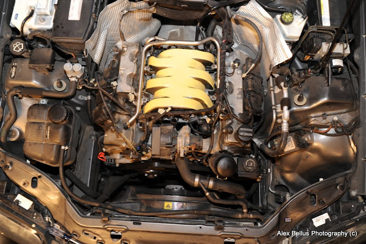
Starting by loosening the screw on the metal band, I removed the fuel rail cover. This involved cutting quite a few zip-ties and was actually a PITA because I found out there were quite a few clips on the underside of the cover that were holding a bunch of wires for the fuel injectors and a few other things.
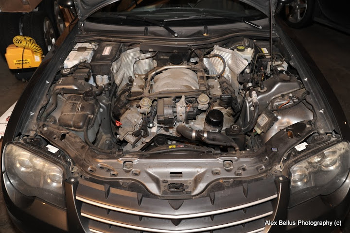
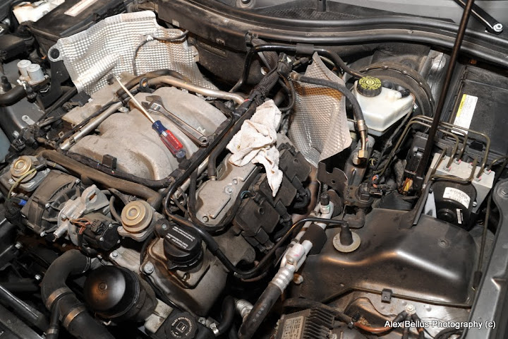
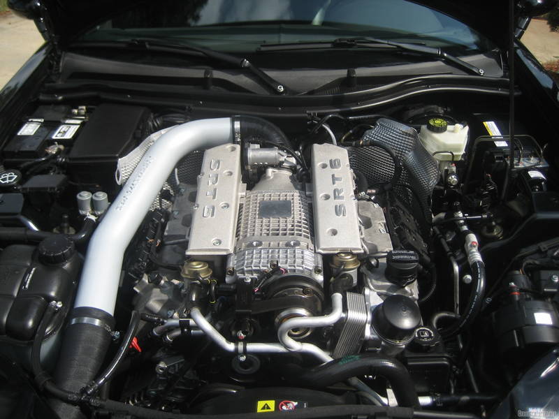
Here's another engine shot with the fuel rail cover off.
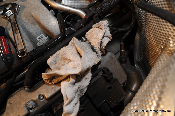
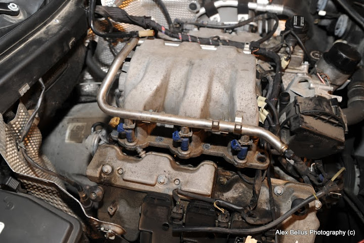
Next step was to drain the fuel out of the fuel rail. I removed the cap on the Schrader valve on the fuel rail at the front of the engine and held a rag in front of it as I let some pressure out of the system there. Then, I unscrewed the fuel feed line into the rail on the back of the engine and let the rest of the fuel drain into a few rags. About half a pop can's worth of fuel came out altogether.
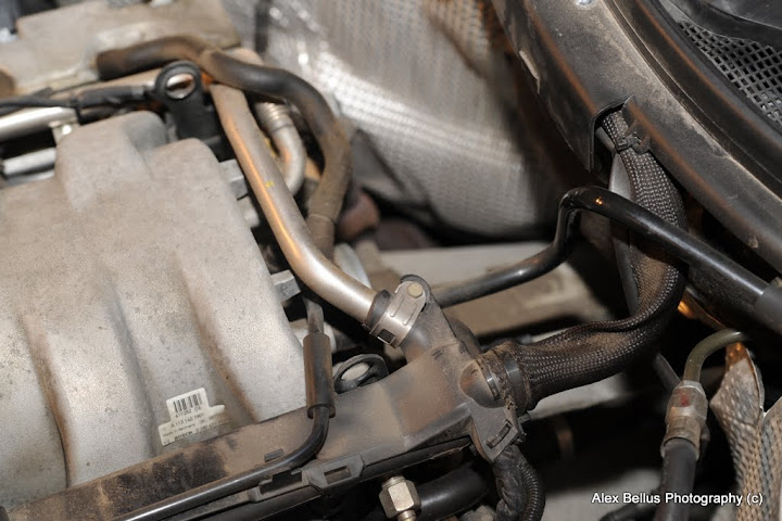
It seemed easier to pull the stock intake manifold with the fuel rail still connected so I left that attached and pulled all the vacuum lines, various connectors for sensors and the fuel injectors, as well as removed the EGR tube out of the back of the intake manifold and removed the connector for the throttle body. I also made sure to remove the two air pump switchover valves on the front of the engine. I made sure to mark each line, sensor, and connector with a piece of tape so I could quickly and easily reconnect everything. This turned out to be a huge time saver when putting everything back together. I also cut out little holes in a cardboard box to place the individual bolts in and labeled where they all went for easy referencing.
Here's a picture of the intake after I loosened it up and was about to pull it.
More to come...
While the parts I bought from Rudy didn't come with any installation instructions, everything was pretty straight forward using a combination of advice from Rudy and the Crossfire service manual I downloaded from this wonderful site. I figured that since I like taking pics, I might as well document the process for anyone else who might want to install this kit themselves.
I'll try to give the best instructions I can to help anyone else out who might be considering doing this themselves in the future.
First off, here's a pic of the stock engine:
And the parts I bought from Rudy to install (stage 2 ported and polished intake manifold, 74mm throttle body, Needwings Single CAI, 17 lb/ft injectors, and NGK spark plugs, plus new gaskets for everything).
First step was to remove the stock airbox and intake tubes.
Next, I removed the MAF and intake piece that connects to the throttle body.
Starting by loosening the screw on the metal band, I removed the fuel rail cover. This involved cutting quite a few zip-ties and was actually a PITA because I found out there were quite a few clips on the underside of the cover that were holding a bunch of wires for the fuel injectors and a few other things.
Here's another engine shot with the fuel rail cover off.
Next step was to drain the fuel out of the fuel rail. I removed the cap on the Schrader valve on the fuel rail at the front of the engine and held a rag in front of it as I let some pressure out of the system there. Then, I unscrewed the fuel feed line into the rail on the back of the engine and let the rest of the fuel drain into a few rags. About half a pop can's worth of fuel came out altogether.
It seemed easier to pull the stock intake manifold with the fuel rail still connected so I left that attached and pulled all the vacuum lines, various connectors for sensors and the fuel injectors, as well as removed the EGR tube out of the back of the intake manifold and removed the connector for the throttle body. I also made sure to remove the two air pump switchover valves on the front of the engine. I made sure to mark each line, sensor, and connector with a piece of tape so I could quickly and easily reconnect everything. This turned out to be a huge time saver when putting everything back together. I also cut out little holes in a cardboard box to place the individual bolts in and labeled where they all went for easy referencing.
Here's a picture of the intake after I loosened it up and was about to pull it.
More to come...
Last edited by Alzilla; Sep 25, 2010 at 02:50 AM.
Thread Starter
Joined: Mar 2010
Posts: 231
Likes: 0
From: Minnesota
Starting to come out!

After I made sure everything was disconnected (I missed a few vacuum hoses the first time around...), I was able to remove the intake manifold and fuel rail as one assembly fairly easily!
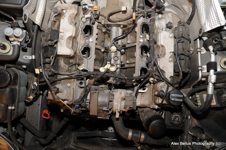
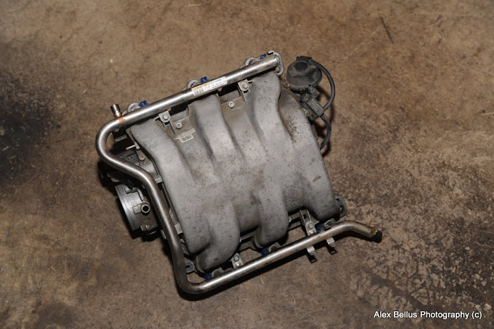
And there it is! The stock intake manifold and fuel rail/injectors are out!
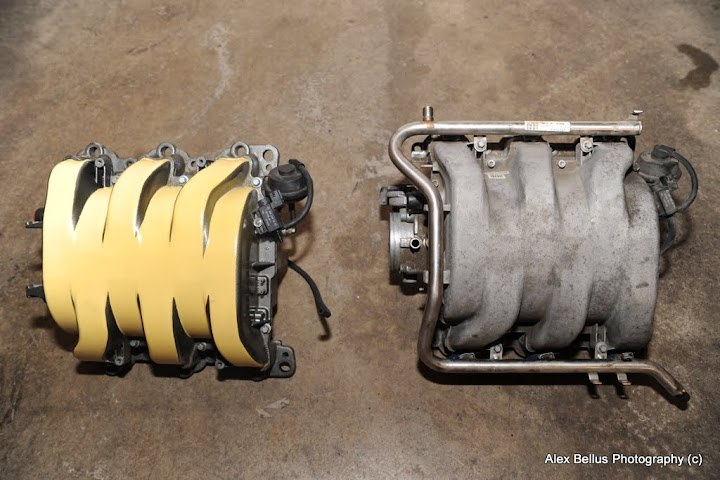
New manifold (left) compared to stock manifold (right)
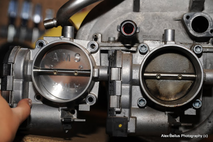
Ported throttle body (left) vs stock throttle body (right)
After installing the bigger throttle body on the new intake manifold, the next step was to remove the fuel rail from the stock intake manifold and install the new injectors. I put a little Vaseline on the o-rings on each end of the injectors before installing them onto the manifold. After placing the injectors into the manifold, I gently pushed the fuel rail on top and used the spacers Rudy gave me to space the fuel rail a little higher since the new injectors are a bit taller than the stock ones.
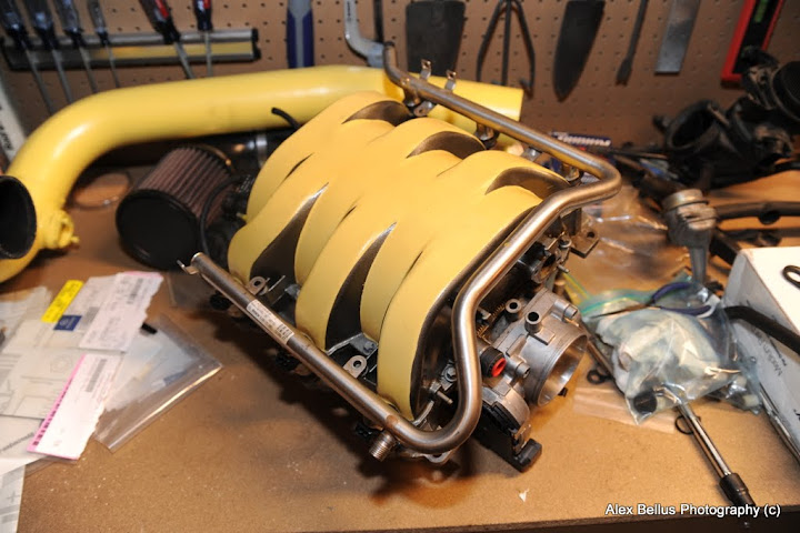
After I got the injectors in, it was a piece of cake to install the manifold! I just placed all the new gaskets where they needed to go and started working in reverse order to how I took everything off.
More to come!
After I made sure everything was disconnected (I missed a few vacuum hoses the first time around...), I was able to remove the intake manifold and fuel rail as one assembly fairly easily!
And there it is! The stock intake manifold and fuel rail/injectors are out!
New manifold (left) compared to stock manifold (right)
Ported throttle body (left) vs stock throttle body (right)
After installing the bigger throttle body on the new intake manifold, the next step was to remove the fuel rail from the stock intake manifold and install the new injectors. I put a little Vaseline on the o-rings on each end of the injectors before installing them onto the manifold. After placing the injectors into the manifold, I gently pushed the fuel rail on top and used the spacers Rudy gave me to space the fuel rail a little higher since the new injectors are a bit taller than the stock ones.
After I got the injectors in, it was a piece of cake to install the manifold! I just placed all the new gaskets where they needed to go and started working in reverse order to how I took everything off.
More to come!
Thread Starter
Joined: Mar 2010
Posts: 231
Likes: 0
From: Minnesota
Since I had the intake manifold, throttle body, and injectors in, the last step was to install the Needswings single CAI! This was the part I was most looking forward to putting in. It's a beautifully made piece and looks like it ought to flow a whole heck of a lot better than the stock airbox.
First step in the installation process was to remove the front grille. Remove the 4 screws along the top of the grille and pop out the 8 or 9 clips at the bottom and it came right out!
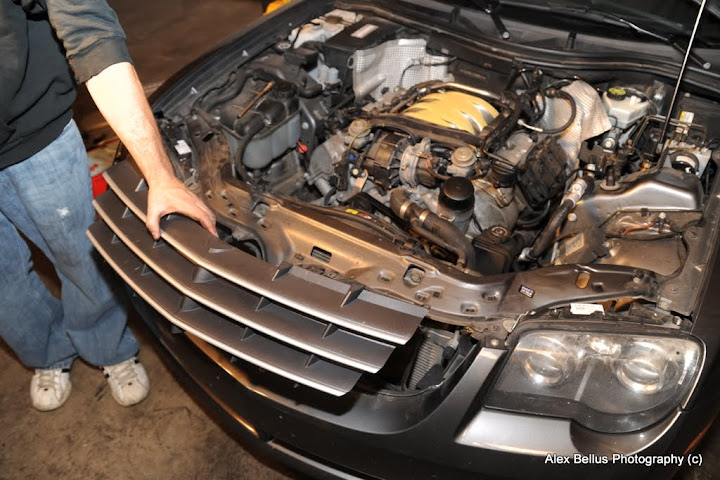
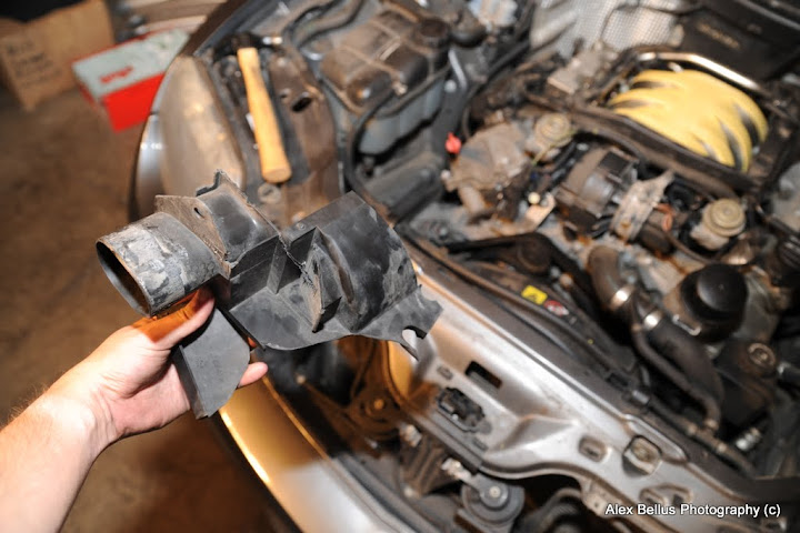
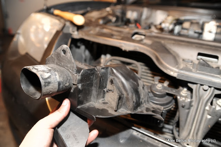
To install the filter in front of the radiator, there is a little plastic piece that wedges in place next to the radiator and is held in place by 2 plugs. Normally, this piece acts as a snorkel for the stock airbox but it was unnecessary and had to be removed to fit the filter element where I wanted it .Rudy suggested that I remove the screw holding the bumper cover on near the right side headlight so that area would have a bit more give and free up some room for yanking on the snorkel. It proved incredibly difficult to remove the plugs holding it in place so I ended up going at it with a small saw to cut pieces away to make it easier to remove! Probably not the recommended way to do it but it was all I could think of at the time. One plug is located at the bottom of the piece and attaches at the metal bumper support. The other plug is located sorta behind the upper metal piece that spans the front of the engine bay (not sure what it's called!) The bottom plug was a pain to get out and I ended up prying it out with a screwdriver eventually. For the upper plug, I had to go in from behind it with a phillips screwdriver and use a hammer to pound it out. Not ideal...
Here's the mangled piece I managed to get out:
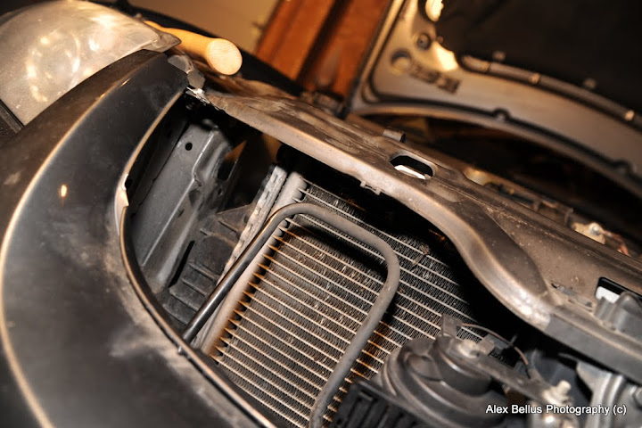
Here's the crevice where it normally belongs. Near the top left of the opening, you can see where the plug was pounded out with the hammer.
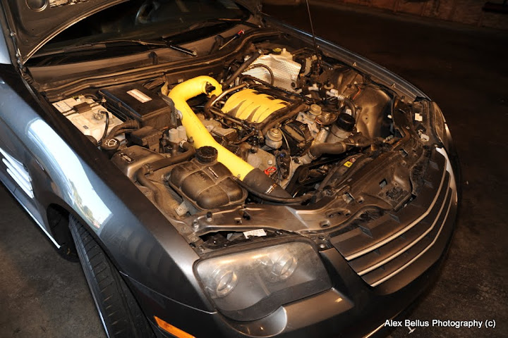
Once I removed that piece, it was pretty straightforward to install the intake. I slid the flexible piping through the new hole and positioned the filter as close to the radiator as I could get it. Then I put the grille back on. After that, it was just a matter of placing the intake tube into the engine bay and attaching the 90* flexible coupler to the throttle body with hose clamps and then sliding the intake tube into the flexible hose I threaded in from in front of the radiator. I made sure to place a few rags over all the areas that could scratch the intake piping because I wanted to protect that yellow finish as well as I could. All in all, I'd say the intake took maybe 30 min tops to install! It was a piece of cake aside from that stupid snorkel!
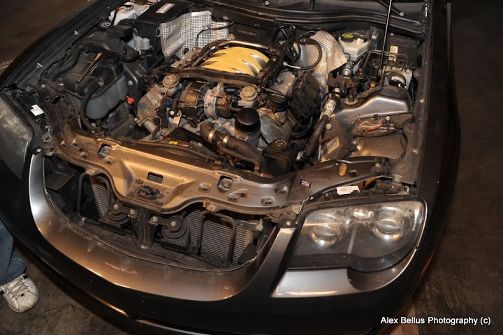
Here's everything in place!


After everything was installed and I doubled checked to make sure I had all the vacuum lines and connectors hooked up in the right spots again, I reconnected the negative battery terminal and started her up! I was a little apprehensive that the ECU would throw a code or two considering how many things I changed but after building up a bit of fuel pressure in the lines again, my Crossfire started right up without any problems! After letting her idle for a minute or two, I closed the hood, and went for a little test drive.
From start to finish, making sure to label everything and take my time, the whole install took about 6.5 hrs. Rudy was very knowledgeable and was able to thoroughly answer any questions I had during the install with excellent details. I really owe him a huge thanks not just for giving me a great deal on the parts, but offering plenty of advice to help me do the install myself.
I think the ECU will still need a bit of time to adjust to the extra air and fuel but the more I drove it today, the more powerful it felt! The intake definitely gives the engine a bit more roar! To be honest, however, it's not quite the kick in the butt I was expecting. It's definitely a little faster now and sounds better to boot, but I guess I was expecting it to blow my socks off and it doesn't quite do that. Then again, maybe I'm just jaded after going for a ride in Tazz's car last weekend!
On the other hand, with a hard launch in first gear, it'll spin the tires all the way to redline and spin them up to about 3,000 RPM in 2nd gear!!! Maybe it just doesn't feel as fast as I was expecting because I can't get enough traction!
The next step (which will be this Spring) will be to send my ECU in for a tune and to install a catback exhaust. I'm also going to paint my brake calipers to match the yellow in the engine bay.
Here's one last shot of the engine bay after my little cruise around town.
I hope this writeup helps!
If you'd like to see more pics or enlarge the photos for more detail, check out my gallery here:
Picasa Web Albums - Alex - Crossfire - B...
First step in the installation process was to remove the front grille. Remove the 4 screws along the top of the grille and pop out the 8 or 9 clips at the bottom and it came right out!
To install the filter in front of the radiator, there is a little plastic piece that wedges in place next to the radiator and is held in place by 2 plugs. Normally, this piece acts as a snorkel for the stock airbox but it was unnecessary and had to be removed to fit the filter element where I wanted it .Rudy suggested that I remove the screw holding the bumper cover on near the right side headlight so that area would have a bit more give and free up some room for yanking on the snorkel. It proved incredibly difficult to remove the plugs holding it in place so I ended up going at it with a small saw to cut pieces away to make it easier to remove! Probably not the recommended way to do it but it was all I could think of at the time. One plug is located at the bottom of the piece and attaches at the metal bumper support. The other plug is located sorta behind the upper metal piece that spans the front of the engine bay (not sure what it's called!) The bottom plug was a pain to get out and I ended up prying it out with a screwdriver eventually. For the upper plug, I had to go in from behind it with a phillips screwdriver and use a hammer to pound it out. Not ideal...
Here's the mangled piece I managed to get out:
Here's the crevice where it normally belongs. Near the top left of the opening, you can see where the plug was pounded out with the hammer.
Once I removed that piece, it was pretty straightforward to install the intake. I slid the flexible piping through the new hole and positioned the filter as close to the radiator as I could get it. Then I put the grille back on. After that, it was just a matter of placing the intake tube into the engine bay and attaching the 90* flexible coupler to the throttle body with hose clamps and then sliding the intake tube into the flexible hose I threaded in from in front of the radiator. I made sure to place a few rags over all the areas that could scratch the intake piping because I wanted to protect that yellow finish as well as I could. All in all, I'd say the intake took maybe 30 min tops to install! It was a piece of cake aside from that stupid snorkel!
Here's everything in place!
After everything was installed and I doubled checked to make sure I had all the vacuum lines and connectors hooked up in the right spots again, I reconnected the negative battery terminal and started her up! I was a little apprehensive that the ECU would throw a code or two considering how many things I changed but after building up a bit of fuel pressure in the lines again, my Crossfire started right up without any problems! After letting her idle for a minute or two, I closed the hood, and went for a little test drive.
From start to finish, making sure to label everything and take my time, the whole install took about 6.5 hrs. Rudy was very knowledgeable and was able to thoroughly answer any questions I had during the install with excellent details. I really owe him a huge thanks not just for giving me a great deal on the parts, but offering plenty of advice to help me do the install myself.
I think the ECU will still need a bit of time to adjust to the extra air and fuel but the more I drove it today, the more powerful it felt! The intake definitely gives the engine a bit more roar! To be honest, however, it's not quite the kick in the butt I was expecting. It's definitely a little faster now and sounds better to boot, but I guess I was expecting it to blow my socks off and it doesn't quite do that. Then again, maybe I'm just jaded after going for a ride in Tazz's car last weekend!
On the other hand, with a hard launch in first gear, it'll spin the tires all the way to redline and spin them up to about 3,000 RPM in 2nd gear!!! Maybe it just doesn't feel as fast as I was expecting because I can't get enough traction!
The next step (which will be this Spring) will be to send my ECU in for a tune and to install a catback exhaust. I'm also going to paint my brake calipers to match the yellow in the engine bay.
Here's one last shot of the engine bay after my little cruise around town.
I hope this writeup helps!
If you'd like to see more pics or enlarge the photos for more detail, check out my gallery here:
Picasa Web Albums - Alex - Crossfire - B...

Senior Member
Joined: Apr 2008
Posts: 3,178
Likes: 24
From: Chicago, IL

Originally Posted by vinnie@tvt
Nice write up. That is the TVT250+ kit though.
When you are ready for the ECU tune shoot us an email. Cost is $250.00 to you for such a great write up.
When you are ready for the ECU tune shoot us an email. Cost is $250.00 to you for such a great write up.
 FP has a TVT265 and he didn't get the larger TB and upgraded intake manifold so which is it?
Senior Member
Joined: Aug 2008
Posts: 3,175
Likes: 16
From: Niagara Falls, Ontario, Canada
Originally Posted by rcompart
Anthony sold this to Paul last year as a TVT300 kit. I'm confused? FP has a TVT265 and he didn't get the larger TB and upgraded intake manifold so which is it?
FP has a TVT265 and he didn't get the larger TB and upgraded intake manifold so which is it?Thread Starter
Joined: Mar 2010
Posts: 231
Likes: 0
From: Minnesota
Originally Posted by rcompart
Anthony sold this to Paul last year as a TVT300 kit. I'm confused? FP has a TVT265 and he didn't get the larger TB and upgraded intake manifold so which is it?
FP has a TVT265 and he didn't get the larger TB and upgraded intake manifold so which is it?BTW Vinnie, I'll probably be sending you my ECU in a couple months once the snow falls and I'm more inclined to let the car sit for awhile.
Last edited by Alzilla; Sep 26, 2010 at 09:34 AM.
Senior Member
Joined: Aug 2009
Posts: 3,459
Likes: 12
From: Warner Robins, GA
Nice writeup Alzilla. You did seem to forget step 1 though.
Step 1: Clean the engine bay - Spray everything down with simple green. Wait 5 minutes and rinse. Let engine area dry. Then spray with CD-2 and let dry.
Results of Step 1:
Step 1: Clean the engine bay - Spray everything down with simple green. Wait 5 minutes and rinse. Let engine area dry. Then spray with CD-2 and let dry.
Results of Step 1:
Last edited by bmorgan; Sep 26, 2010 at 01:50 AM.
Senior Member
Joined: Apr 2008
Posts: 3,178
Likes: 24
From: Chicago, IL
Originally Posted by TVT_DESIGN
We've made ample progress on our N/A modifications over the winter. We had a chance to play around a number of AMG and non-AMG N/A motors in all types of cars and see what works. All of this playing has paid off.
Our TVT300 will be in addition to our TVT265 kit and will add the remainder of "bolt-ons" available. Our goal for this kit was to increase the powerband and keep the low and midrange pull, but also allow the engine to breather better on the top end.
This kit will be sold with out an exhaust, but will be tested with one. The reason we are doing this is because many of our customers already have exhausts on their cars, and if they don't a custom exhaust is fairly cost effective. However, we will be offering Magnaflow cat backs and race cats for those interested in piecing a system together.
Our Kit will include the following:
Pricing has not been established yet, but we are looking to keep it under 3K for the upgrade and around 4K for the whole package. Prices are subject to change as we continue to finalize the products.
I will post up some pics of the TB and manifold. Dyno results will follow.
Our TVT300 will be in addition to our TVT265 kit and will add the remainder of "bolt-ons" available. Our goal for this kit was to increase the powerband and keep the low and midrange pull, but also allow the engine to breather better on the top end.
This kit will be sold with out an exhaust, but will be tested with one. The reason we are doing this is because many of our customers already have exhausts on their cars, and if they don't a custom exhaust is fairly cost effective. However, we will be offering Magnaflow cat backs and race cats for those interested in piecing a system together.
Our Kit will include the following:
- Ported/Polished Intake Manifold Stage 2
- 74mm Throttle Body
- Catch Can
- Tubular Headers
- Tune/Re-tune
- TVT265 (if not purchased)
Pricing has not been established yet, but we are looking to keep it under 3K for the upgrade and around 4K for the whole package. Prices are subject to change as we continue to finalize the products.
I will post up some pics of the TB and manifold. Dyno results will follow.
Senior Member
Joined: Oct 2008
Posts: 923
Likes: 11
From: Folsom Prison
Originally Posted by rcompart
I don't see anything about cams or head work in this thread and Anthony said that the headers didn't make any power when he tuned Paul's car at Carlisle last year. He sold this to Paul as a TVT300 so you can't say it wasn't released. If it wasn't, then he owes Paul an explanation as to why he sold him a 250+ kit and called it a TVT300!

Joined: Apr 2015
Posts: 1
Likes: 0
From: California
I don't see anything about cams or head work in this thread and Anthony said that the headers didn't make any power when he tuned Paul's car at Carlisle last year. He sold this to Paul as a TVT300 so you can't say it wasn't released. If it wasn't, then he owes Paul an explanation as to why he sold him a 250+ kit and called it a TVT300!
Administrator / Senior Member / Retired
Joined: Jul 2007
Posts: 18,108
Likes: 1,602
From: Aurora , ILL
First of all welcome to the forum
This thread dates back to 2010
TVT is no longer here
The only way you might find TVT parts might be through a forum member here who has some TVT stuff sitting around collecting dust
I suggest you take a look at Needswings.com
Rob (Owner) is a member here and provides many great aftermarket parts for our Crossfires
Good luck with the upgrades and modding
Gary
Last edited by Valk; Apr 28, 2015 at 09:32 PM.
Senior Member
Joined: Apr 2006
Posts: 25,432
Likes: 648
From: Ontario
TVT was all wishful thinking, that's why they went t!ts up.

Thread
Thread Starter
Forum
Replies
Last Post
2005 Ragtop
Wheels, Brakes, Tires and Suspension
7
Oct 3, 2015 03:01 PM
Currently Active Users Viewing This Thread: 1 (0 members and 1 guests)